Tag Archives: reducer

China Sinotruk Axle Parts Medium Axle Main Reducer with Bearing Cover Assy 711-35301-6109 axle cv joint

Solution Description

Sinotruk Axle Parts  Medium Axle Main Reducer With bearing Cover Assy 711-35301-6109


Firm ChinaMach Industry Co.,Ltd
Brand name SINOTRUK HOWO/WEICHAI/Man/SHACMAN/FAW/FOTON/AUMAN/NORTHBENZ/SANY/SHXIHU (WEST LAKE) DIS.I/SDLG
Quality Unique element/OE element
Payment expression T/T L/C , Flexible billing strategy
Packing Standard packing

We can provide:
TRUCK
Income Chinese vehicles and building equipment,Provide modificationsu,pgrades, consulting services
SPARE TRUCK
Provide China Truck spare elements and building machinery areas. Goods Include:  Sinotruk HOWO, CZPT , Fonton, Shacman,  SHXIHU (WEST LAKE) DIS.I, CZPT ,SDLG
Services
Offer cargo warehousing, packaging, shipping and delivery and export company services
Agent procurement, inspection The inspection agency  


US $1
/ Piece
|
1 Piece

(Min. Order)

###

Certification: ISO9001
Driving System Parts: Frame
Electrical System Parts: Starting System
Brake System Parts: Brake
Transmission System Parts: Transmission Shaft
Steering System Parts: Steering Transmission Device

###

Samples:
US$ 1/Piece
1 Piece(Min.Order)

|
Request Sample

###

Customization:

###

Company ChinaMach Industry Co.,Ltd
Brand SINOTRUK HOWO/WEICHAI/MAN/SHACMAN/FAW/FOTON/AUMAN/NORTHBENZ/SANY/SHANTUI/SDLG
QUALITY Original part/OE part
Payment term T/T L/C , Flexible billing method
Packing Standard packing

Axle Types

An axle is the central shaft of a rotating gear or wheel. Axles are either fixed to the wheels or mounted directly to the vehicle. They rotate with the wheels and can be equipped with bearings for smooth operation. Axle types include Czpt axles, Drop out axles, and Splines. Each has a unique design and function.

Spindles

The spindles on a vehicle’s axle are the main components that connect the wheels to the axle. They mount the wheels on the axle and fasten the braking system to the axle assembly. The spindles are fastened to the axle assembly with king pins and ball joints. They also fasten the wheel hub to the spindle via a castelated nut. In both applications, axle spindles are pivot points that are used to make turning motion possible.
There are three types of spindles for an axle. Typically, the spindles are bolted to the ends of a tubular axle, which is suspended by springs. The third type is a short stub axle, which uses a torsion beam to help the axle maintain a smooth ride over bumpy terrain.
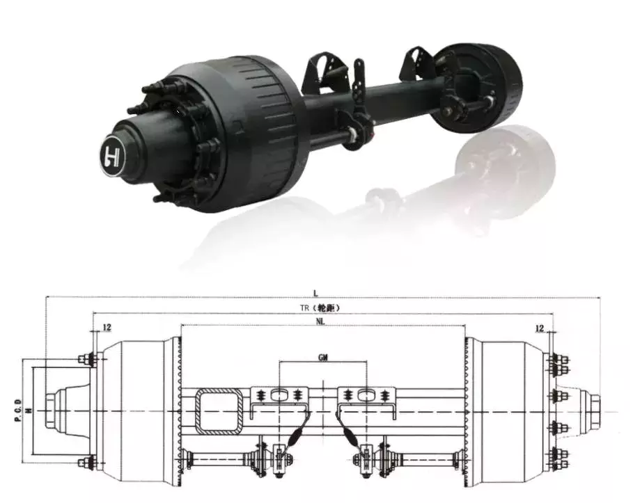
Axles

Czpt axles

Czpt axles are available in a variety of configurations. From beam-to-independent designs to single-point-to-double-point designs, there’s a Czpt axle to fit your needs. These axles are designed to provide maximum power in a small package. Czpt has a proven track record of innovation and durability.
Czpt axles are found in front-end steering vehicles and heavy-duty pickups. Some models only use the front axle. There are also Czpt axles for light-duty pickups. You can easily recognize a Czpt axle by its shape. Some online sources offer diagrams to help you identify the axle.
Among the most popular Czpt axles are the Czpt 60 and the Czpt 44. Both models are desirable in their own right. You can order Czpt axle parts from the Czpt website. These products include u joints, differential cases, and loc pins. These parts can be purchased online, and they will be delivered right to your door.
In addition to the Czpt 60 front axle, Czpt axles also feature great aftermarket support. They can be upgraded with locking differentials, limited slip differentials, and high-capacity differential covers. They also feature heat-sinks that keep the axle cool. Czpt axles are also compatible with nearly every traction aid in the market.
Czpt is a global leader in driveline products and genuine service parts. With over a century of experience manufacturing quality products, Czpt axles provide performance and reliability.
Axles

Drop out axles

Drop out axles are crucial for mounting a front wheel to a bike. If the axles are not present, the wheel will not be able to be mounted. These dropouts are made of either steel or aluminum. They are 5.8mm thick. Axles with quick release axle hubs are compatible with steel dropouts.
Axle manufacturers make different dropout axles that are compatible with different axle sizes. These axles are available in a wide range of styles. The Shimano modular dropout, for example, is available in three main axle specifications: Road, Track, and Maxle. These dropouts are also available with different axle pinions.
Drop out axles can be quick release or through. Quick release axles are lighter than thru axles. They weigh approximately 60 to 80 grams. The difference between quick release and thru axles is in the thread pitch. Quick release axles have a smaller pitch than thru axles, which allows for easier installation and removal.
Thru axles are a popular choice for mountain bikes. They prevent the front wheel from coming out while riding. They are more secure and can prevent a wheel from coming off when moving. They are usually made of a thicker rod and screw into the frame. Both types of dropouts have their advantages and disadvantages. You should choose the type that works best for your needs. This is a decision that you will have to make on your own.
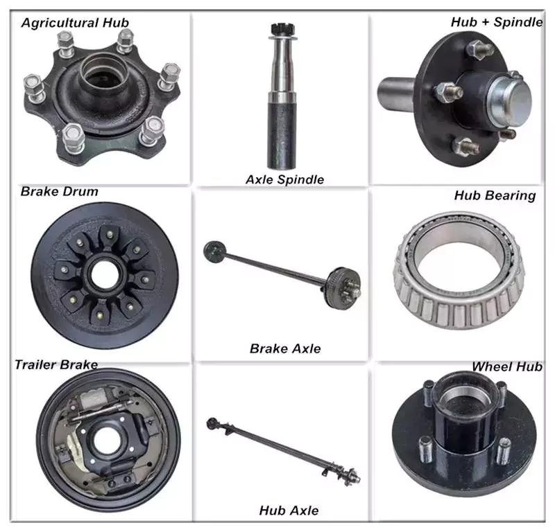
Axles

CV joints

When your vehicle is in motion, the CV joints on your axle transfer torque to the wheels. Although these joints come in a wide variety of designs, they all contain a bearing assembly that allows them to move. These joints are protected by a rubber boot that is filled with grease to keep them lubricated. When they become worn, they can cause your car to shudder and vibrate while accelerating.
To avoid joint failure, it is important to keep the CV joints free of road debris. Luckily, the boots are made of durable rubber, and a good quality one can last 100,000 miles. Unfortunately, if the rubber boot is torn, dirt and moisture can leak into the joint. Therefore, it’s important to inspect the boots regularly, and replace them if necessary.
Damaged CV joints can make control of your vehicle extremely difficult. They can also cause your steering wheel to jerk when you’re accelerating, increasing the risk of an accident. A damaged CV joint can also lead to axle separation, which can cause massive damage and a serious safety risk. However, if you don’t have the funds to replace the joint, you can repair the problem by applying a sleeve.
Unlike other drive systems, CV axles can transfer torque at an angle. This is possible because of the constant velocity joints. They’re akin to the univeersal joints on tail shafts, except they work on a much larger angle. This allows the drive shaft to transfer torque to the front wheels smoothly. It also allows the axle to move up and down.
A damaged CV axle will make a characteristic clicking sound when you’re turning the vehicle. This noise is very distinctive and can only be heard when the vehicle is in motion. If you hear this noise, then the joint is worn and is in danger of failure. If this noise is loud and consistent, you’ll need to replace it.
China Sinotruk Axle Parts Medium Axle Main Reducer with Bearing Cover Assy 711-35301-6109     axle cv jointChina Sinotruk Axle Parts Medium Axle Main Reducer with Bearing Cover Assy 711-35301-6109     axle cv joint
editor by czh 2022-12-13

China supplier F/FF/Fa/Faf57 Parallel Shaft Helical Gear Reducer with Hot selling

Product Description

Overview
———————————————————————————————————————————————————————————————————————————————–
Quick Details
Gearing Arrangement:    Helical                                                                                                                Brand Name:                   EED
Input Speed:                     1400 rpm                                                                                                           Output Speed:                 4.8 rpm to 1075 rpm
Rated Power:                    0.12 ~ 160KW                                                                                                  Gear Ratio:                       2.64-251.25
Color:                                 Blue/Silver or on request                                                                                Origin:                               ZHangZhoug, China (Mainland)         
Warranty:                           1 Year                                                                                                                Application:                      Industry    
———————————————————————————————————————————————————————————————————————————————–
Supply Ability
Supply Ability:                   20000 Piece/Pieces per Month
Extra Service:                    OEM is welcome         
QC System:                        ISO9001:2008
———————————————————————————————————————————————————————————————————————————————–
Packaging & Delivery
Package:                            Wooden box/Paper carton    
Port:                                    HangZhou/ZheJiang  or on request     
———————————————————————————————————————————————————————————————————————————————–

1. F series parallel shaft helical box is based on the design of parallel shaft tructure, which have a center distance
between input and output shaft who are parallel.

2. Compact construction, steady running, high transmission efficiency, strong carrying capacity.

3. The material of gears is 20CrMnTi alloy steel and the hardness can reach to HRC58; ~ 62; After tempering, ce-
mentiting,quenching etc. Heat treatment. All the gears are processed by accurate grinding and the precision
can reach to grade 6~5.

4. Installation: Foot-mounted, flange, torque arm and so on; Output type: Solid shaft, hollow shaft and can choose
to add
one-key, spline, or shrink disc connection. Input Model: Directly connected with motor, flange input or shaft input.
Markets

About CZPT since 1984
HangZhou Melchizedek Import & Export Co., Ltd. is a leader manufactur in mechanism field and punching/stamp
ing field since 1984. Our main product, NMRV worm gear speed reducer and series helical gearbox, XDR,
XDF, XDK, XDShave reached the advanced technique index of the congeneric European and Janpanese produc
ts, We offer standard gears, sprockets, chains, pulleys, couplings, bushes and so on. We also can accept orders
of  non-standard products, such as gears, shafts, punching parts ect, according to customers’ Drawings or sam-
ples. 

Our company has complete set of equipment including CNC, lathes, milling machines, gear hobbing machine, g-
ear grinding machine, gear honing machine, gear shaping machine, worm grinder, grinding machines, drilling m-
achines, boringmachines, planer, drawing benches, punches, hydraulic presses, plate shearing machines and s-
o on. We have advanced testing equipments also. 

Our company has established favorable cooperation relationships with sub-suppliers involving casting, raw mat-
erial, heat treatment, surface finishing and so on.


The Different Types of Splines in a Splined Shaft

A splined shaft is a machine component with internal and external splines. The splines are formed in 4 different ways: Involute, Parallel, Serrated, and Ball. You can learn more about each type of spline in this article. When choosing a splined shaft, be sure to choose the right 1 for your application. Read on to learn about the different types of splines and how they affect the shaft’s performance.
splineshaft

Involute splines

Involute splines in a splined shaft are used to secure and extend mechanical assemblies. They are smooth, inwardly curving grooves that resist separation during operation. A shaft with involute splines is often longer than the shaft itself. This feature allows for more axial movement. This is beneficial for many applications, especially in a gearbox.
The involute spline is a shaped spline, similar to a parallel spline. It is angled and consists of teeth that create a spiral pattern that enables linear and rotatory motion. It is distinguished from other splines by the serrations on its flanks. It also has a flat top. It is a good option for couplers and other applications where angular movement is necessary.
Involute splines are also called involute teeth because of their shape. They are flat on the top and curved on the sides. These teeth can be either internal or external. As a result, involute splines provide greater surface contact, which helps reduce stress and fatigue. Regardless of the shape, involute splines are generally easy to machine and fit.
Involute splines are a type of splines that are used in splined shafts. These splines have different names, depending on their diameters. An example set of designations is for a 32-tooth male spline, a 2,500-tooth module, and a 30 degree pressure angle. An example of a female spline, a fillet root spline, is used to describe the diameter of the splined shaft.
The effective tooth thickness of splines is dependent on the number of keyways and the type of spline. Involute splines in splined shafts should be designed to engage 25 to 50 percent of the spline teeth during the coupling. Involute splines should be able to withstand the load without cracking.

Parallel splines

Parallel splines are formed on a splined shaft by putting 1 or more teeth into another. The male spline is positioned at the center of the female spline. The teeth of the male spline are also parallel to the shaft axis, but a common misalignment causes the splines to roll and tilt. This is common in many industrial applications, and there are a number of ways to improve the performance of splines.
Typically, parallel splines are used to reduce friction in a rotating part. The splines on a splined shaft are narrower on the end face than the interior, which makes them more prone to wear. This type of spline is used in a variety of industries, such as machinery, and it also allows for greater efficiency when transmitting torque.
Involute splines on a splined shaft are the most common. They have equally spaced teeth, and are therefore less likely to crack due to fatigue. They also tend to be easy to cut and fit. However, they are not the best type of spline. It is important to understand the difference between parallel and involute splines before deciding on which spline to use.
The difference between splined and involute splines is the size of the grooves. Involute splines are generally larger than parallel splines. These types of splines provide more torque to the gear teeth and reduce stress during operation. They are also more durable and have a longer life span. And because they are used on farm machinery, they are essential in this type of application.
splineshaft

Serrated splines

A Serrated Splined Shaft has several advantages. This type of shaft is highly adjustable. Its large number of teeth allows large torques, and its shorter tooth width allows for greater adjustment. These features make this type of shaft an ideal choice for applications where accuracy is critical. Listed below are some of the benefits of this type of shaft. These benefits are just a few of the advantages. Learn more about this type of shaft.
The process of hobbing is inexpensive and highly accurate. It is useful for external spline shafts, but is not suitable for internal splines. This type of process forms synchronized shapes on the shaft, reducing the manufacturing cycle and stabilizing the relative phase between spline and thread. It uses a grinding wheel to shape the shaft. CZPT Manufacturing has a large inventory of Serrated Splined Shafts.
The teeth of a Serrated Splined Shaft are designed to engage with the hub over the entire circumference of the shaft. The teeth of the shaft are spaced uniformly around the spline, creating a multiple-tooth point of contact over the entire length of the shaft. The results of these analyses are usually satisfactory. But there are some limitations. To begin with, the splines of the Serrated Splined Shaft should be chosen carefully. If the application requires large-scale analysis, it may be necessary to modify the design.
The splines of the Serrated Splined Shaft are also used for other purposes. They can be used to transmit torque to another device. They also act as an anti-rotational device and function as a linear guide. Both the design and the type of splines determine the function of the Splined Shaft. In the automobile industry, they are used in vehicles, aerospace, earth-moving machinery, and many other industries.

Ball splines

The invention relates to a ball-spinned shaft. The shaft comprises a plurality of balls that are arranged in a series and are operatively coupled to a load path section. The balls are capable of rolling endlessly along the path. This invention also relates to a ball bearing. Here, a ball bearing is 1 of the many types of gears. The following discussion describes the features of a ball bearing.
A ball-splined shaft assembly comprises a shaft with at least 1 ball-spline groove and a plurality of circumferential step grooves. The shaft is held in a first holding means that extends longitudinally and is rotatably held by a second holding means. Both the shaft and the first holding means are driven relative to 1 another by a first driving means. It is possible to manufacture a ball-splined shaft in a variety of ways.
A ball-splined shaft features a nut with recirculating balls. The ball-splined nut rides in these grooves to provide linear motion while preventing rotation. A splined shaft with a nut that has recirculating balls can also provide rotary motion. A ball splined shaft also has higher load capacities than a ball bushing. For these reasons, ball splines are an excellent choice for many applications.
In this invention, a pair of ball-spinned shafts are housed in a box under a carrier device 40. Each of the 2 shafts extends along a longitudinal line of arm 50. One end of each shaft is supported rotatably by a slide block 56. The slide block also has a support arm 58 that supports the center arm 50 in a cantilever fashion.
splineshaft

Sector no-go gage

A no-go gauge is a tool that checks the splined shaft for oversize. It is an effective way to determine the oversize condition of a splined shaft without removing the shaft. It measures external splines and serrations. The no-go gage is available in sizes ranging from 19mm to 130mm with a 25mm profile length.
The sector no-go gage has 2 groups of diametrally opposed teeth. The space between them is manufactured to a maximum space width and the tooth thickness must be within a predetermined tolerance. This gage would be out of tolerance if the splines were measured with a pin. The dimensions of this splined shaft can be found in the respective ANSI or DIN standards.
The go-no-go gage is useful for final inspection of thread pitch diameter. It is also useful for splined shafts and threaded nuts. The thread of a screw must match the contour of the go-no-go gage head to avoid a no-go condition. There is no substitute for a quality machine. It is an essential tool for any splined shaft and fastener manufacturer.
The NO-GO gage can detect changes in tooth thickness. It can be calibrated under ISO17025 standards and has many advantages over a non-go gage. It also gives a visual reference of the thickness of a splined shaft. When the teeth match, the shaft is considered ready for installation. It is a critical process. In some cases, it is impossible to determine the precise length of the shaft spline.
The 45-degree pressure angle is most commonly used for axles and torque-delivering members. This pressure angle is the most economical in terms of tool life, but the splines will not roll neatly like a 30 degree angle. The 45-degree spline is more likely to fall off larger than the other two. Oftentimes, it will also have a crowned look. The 37.5 degree pressure angle is a compromise between the other 2 pressure angles. It is often used when the splined shaft material is harder than usual.

China supplier F/FF/Fa/Faf57 Parallel Shaft Helical Gear Reducer     with Hot sellingChina supplier F/FF/Fa/Faf57 Parallel Shaft Helical Gear Reducer     with Hot selling

China Hot selling Standard F Series Parallel Shaft Helical Gearbox Speed Reducer near me factory

Product Description

Overview
———————————————————————————————————————————————————————————————————————————————–
Quick Details
Gearing Arrangement:    Helical                                                                                                                Brand Name:                   EED
Input Speed:                     1400 rpm                                                                                                           Output Speed:                 4.8 rpm to 1075 rpm
Rated Power:                    0.12 ~ 160KW                                                                                                  Gear Ratio:                       2.64-251.25
Color:                                 Blue/Silver or on request                                                                                Origin:                               ZHangZhoug, China (Mainland)         
Warranty:                           1 Year                                                                                                                Application:                      Industry    
———————————————————————————————————————————————————————————————————————————————–
Supply Ability
Supply Ability:                   20000 Piece/Pieces per Month
Extra Service:                    OEM is welcome         
QC System:                        ISO9001:2008
———————————————————————————————————————————————————————————————————————————————–
Packaging & Delivery
Package:                            Wooden box/Paper carton    
Port:                                    HangZhou/ZheJiang  or on request     
———————————————————————————————————————————————————————————————————————————————–

1. F series parallel shaft helical box is based on the design of parallel shaft tructure, which have a center distance
between input and output shaft who are parallel.

2. Compact construction, steady running, high transmission efficiency, strong carrying capacity.

3. The material of gears is 20CrMnTi alloy steel and the hardness can reach to HRC58; ~ 62; After tempering, ce-
mentiting,quenching etc. Heat treatment. All the gears are processed by accurate grinding and the precision
can reach to grade 6~5.

4. Installation: Foot-mounted, flange, torque arm and so on; Output type: Solid shaft, hollow shaft and can choose
to add
one-key, spline, or shrink disc connection. Input Model: Directly connected with motor, flange input or shaft input.
Markets

About CZPT since 1984
HangZhou Melchizedek Import & Export Co., Ltd. is a leader manufactur in mechanism field and punching/stamp
ing field since 1984. Our main product, NMRV worm gear speed reducer and series helical gearbox, XDR,
XDF, XDK, XDShave reached the advanced technique index of the congeneric European and Janpanese produc
ts, We offer standard gears, sprockets, chains, pulleys, couplings, bushes and so on. We also can accept orders
of  non-standard products, such as gears, shafts, punching parts ect, according to customers’ Drawings or sam-
ples. 

Our company has complete set of equipment including CNC, lathes, milling machines, gear hobbing machine, g-
ear grinding machine, gear honing machine, gear shaping machine, worm grinder, grinding machines, drilling m-
achines, boringmachines, planer, drawing benches, punches, hydraulic presses, plate shearing machines and s-
o on. We have advanced testing equipments also. 

Our company has established favorable cooperation relationships with sub-suppliers involving casting, raw mat-
erial, heat treatment, surface finishing and so on.


Stiffness and Torsional Vibration of Spline-Couplings

In this paper, we describe some basic characteristics of spline-coupling and examine its torsional vibration behavior. We also explore the effect of spline misalignment on rotor-spline coupling. These results will assist in the design of improved spline-coupling systems for various applications. The results are presented in Table 1.
splineshaft

Stiffness of spline-coupling

The stiffness of a spline-coupling is a function of the meshing force between the splines in a rotor-spline coupling system and the static vibration displacement. The meshing force depends on the coupling parameters such as the transmitting torque and the spline thickness. It increases nonlinearly with the spline thickness.
A simplified spline-coupling model can be used to evaluate the load distribution of splines under vibration and transient loads. The axle spline sleeve is displaced a z-direction and a resistance moment T is applied to the outer face of the sleeve. This simple model can satisfy a wide range of engineering requirements but may suffer from complex loading conditions. Its asymmetric clearance may affect its engagement behavior and stress distribution patterns.
The results of the simulations show that the maximum vibration acceleration in both Figures 10 and 22 was 3.03 g/s. This results indicate that a misalignment in the circumferential direction increases the instantaneous impact. Asymmetry in the coupling geometry is also found in the meshing. The right-side spline’s teeth mesh tightly while those on the left side are misaligned.
Considering the spline-coupling geometry, a semi-analytical model is used to compute stiffness. This model is a simplified form of a classical spline-coupling model, with submatrices defining the shape and stiffness of the joint. As the design clearance is a known value, the stiffness of a spline-coupling system can be analyzed using the same formula.
The results of the simulations also show that the spline-coupling system can be modeled using MASTA, a high-level commercial CAE tool for transmission analysis. In this case, the spline segments were modeled as a series of spline segments with variable stiffness, which was calculated based on the initial gap between spline teeth. Then, the spline segments were modelled as a series of splines of increasing stiffness, accounting for different manufacturing variations. The resulting analysis of the spline-coupling geometry is compared to those of the finite-element approach.
Despite the high stiffness of a spline-coupling system, the contact status of the contact surfaces often changes. In addition, spline coupling affects the lateral vibration and deformation of the rotor. However, stiffness nonlinearity is not well studied in splined rotors because of the lack of a fully analytical model.
splineshaft

Characteristics of spline-coupling

The study of spline-coupling involves a number of design factors. These include weight, materials, and performance requirements. Weight is particularly important in the aeronautics field. Weight is often an issue for design engineers because materials have varying dimensional stability, weight, and durability. Additionally, space constraints and other configuration restrictions may require the use of spline-couplings in certain applications.
The main parameters to consider for any spline-coupling design are the maximum principal stress, the maldistribution factor, and the maximum tooth-bearing stress. The magnitude of each of these parameters must be smaller than or equal to the external spline diameter, in order to provide stability. The outer diameter of the spline must be at least 4 inches larger than the inner diameter of the spline.
Once the physical design is validated, the spline coupling knowledge base is created. This model is pre-programmed and stores the design parameter signals, including performance and manufacturing constraints. It then compares the parameter values to the design rule signals, and constructs a geometric representation of the spline coupling. A visual model is created from the input signals, and can be manipulated by changing different parameters and specifications.
The stiffness of a spline joint is another important parameter for determining the spline-coupling stiffness. The stiffness distribution of the spline joint affects the rotor’s lateral vibration and deformation. A finite element method is a useful technique for obtaining lateral stiffness of spline joints. This method involves many mesh refinements and requires a high computational cost.
The diameter of the spline-coupling must be large enough to transmit the torque. A spline with a larger diameter may have greater torque-transmitting capacity because it has a smaller circumference. However, the larger diameter of a spline is thinner than the shaft, and the latter may be more suitable if the torque is spread over a greater number of teeth.
Spline-couplings are classified according to their tooth profile along the axial and radial directions. The radial and axial tooth profiles affect the component’s behavior and wear damage. Splines with a crowned tooth profile are prone to angular misalignment. Typically, these spline-couplings are oversized to ensure durability and safety.

Stiffness of spline-coupling in torsional vibration analysis

This article presents a general framework for the study of torsional vibration caused by the stiffness of spline-couplings in aero-engines. It is based on a previous study on spline-couplings. It is characterized by the following 3 factors: bending stiffness, total flexibility, and tangential stiffness. The first criterion is the equivalent diameter of external and internal splines. Both the spline-coupling stiffness and the displacement of splines are evaluated by using the derivative of the total flexibility.
The stiffness of a spline joint can vary based on the distribution of load along the spline. Variables affecting the stiffness of spline joints include the torque level, tooth indexing errors, and misalignment. To explore the effects of these variables, an analytical formula is developed. The method is applicable for various kinds of spline joints, such as splines with multiple components.
Despite the difficulty of calculating spline-coupling stiffness, it is possible to model the contact between the teeth of the shaft and the hub using an analytical approach. This approach helps in determining key magnitudes of coupling operation such as contact peak pressures, reaction moments, and angular momentum. This approach allows for accurate results for spline-couplings and is suitable for both torsional vibration and structural vibration analysis.
The stiffness of spline-coupling is commonly assumed to be rigid in dynamic models. However, various dynamic phenomena associated with spline joints must be captured in high-fidelity drivetrain models. To accomplish this, a general analytical stiffness formulation is proposed based on a semi-analytical spline load distribution model. The resulting stiffness matrix contains radial and tilting stiffness values as well as torsional stiffness. The analysis is further simplified with the blockwise inversion method.
It is essential to consider the torsional vibration of a power transmission system before selecting the coupling. An accurate analysis of torsional vibration is crucial for coupling safety. This article also discusses case studies of spline shaft wear and torsionally-induced failures. The discussion will conclude with the development of a robust and efficient method to simulate these problems in real-life scenarios.
splineshaft

Effect of spline misalignment on rotor-spline coupling

In this study, the effect of spline misalignment in rotor-spline coupling is investigated. The stability boundary and mechanism of rotor instability are analyzed. We find that the meshing force of a misaligned spline coupling increases nonlinearly with spline thickness. The results demonstrate that the misalignment is responsible for the instability of the rotor-spline coupling system.
An intentional spline misalignment is introduced to achieve an interference fit and zero backlash condition. This leads to uneven load distribution among the spline teeth. A further spline misalignment of 50um can result in rotor-spline coupling failure. The maximum tensile root stress shifted to the left under this condition.
Positive spline misalignment increases the gear mesh misalignment. Conversely, negative spline misalignment has no effect. The right-handed spline misalignment is opposite to the helix hand. The high contact area is moved from the center to the left side. In both cases, gear mesh is misaligned due to deflection and tilting of the gear under load.
This variation of the tooth surface is measured as the change in clearance in the transverse plain. The radial and axial clearance values are the same, while the difference between the 2 is less. In addition to the frictional force, the axial clearance of the splines is the same, which increases the gear mesh misalignment. Hence, the same procedure can be used to determine the frictional force of a rotor-spline coupling.
Gear mesh misalignment influences spline-rotor coupling performance. This misalignment changes the distribution of the gear mesh and alters contact and bending stresses. Therefore, it is essential to understand the effects of misalignment in spline couplings. Using a simplified system of helical gear pair, Hong et al. examined the load distribution along the tooth interface of the spline. This misalignment caused the flank contact pattern to change. The misaligned teeth exhibited deflection under load and developed a tilting moment on the gear.
The effect of spline misalignment in rotor-spline couplings is minimized by using a mechanism that reduces backlash. The mechanism comprises cooperably splined male and female members. One member is formed by 2 coaxially aligned splined segments with end surfaces shaped to engage in sliding relationship. The connecting device applies axial loads to these segments, causing them to rotate relative to 1 another.

China Hot selling Standard F Series Parallel Shaft Helical Gearbox Speed Reducer     near me factory China Hot selling Standard F Series Parallel Shaft Helical Gearbox Speed Reducer     near me factory

China best F/FF/Fa/Faf47 Parallel Shaft Helical Gear Reducer with Hot selling

Product Description

Overview
———————————————————————————————————————————————————————————————————————————————–
Quick Details
Gearing Arrangement:    Helical                                                                                                                Brand Name:                   EED
Input Speed:                     1400 rpm                                                                                                           Output Speed:                 4.8 rpm to 1075 rpm
Rated Power:                    0.12 ~ 160KW                                                                                                  Gear Ratio:                       2.64-251.25
Color:                                 Blue/Silver or on request                                                                                Origin:                               ZHangZhoug, China (Mainland)         
Warranty:                           1 Year                                                                                                                Application:                      Industry    
———————————————————————————————————————————————————————————————————————————————–
Supply Ability
Supply Ability:                   20000 Piece/Pieces per Month
Extra Service:                    OEM is welcome         
QC System:                        ISO9001:2008
———————————————————————————————————————————————————————————————————————————————–
Packaging & Delivery
Package:                            Wooden box/Paper carton    
Port:                                    HangZhou/ZheJiang  or on request     
———————————————————————————————————————————————————————————————————————————————–

1. F series parallel shaft helical box is based on the design of parallel shaft tructure, which have a center distance
between input and output shaft who are parallel.

2. Compact construction, steady running, high transmission efficiency, strong carrying capacity.

3. The material of gears is 20CrMnTi alloy steel and the hardness can reach to HRC58; ~ 62; After tempering, ce-
mentiting,quenching etc. Heat treatment. All the gears are processed by accurate grinding and the precision
can reach to grade 6~5.

4. Installation: Foot-mounted, flange, torque arm and so on; Output type: Solid shaft, hollow shaft and can choose
to add
one-key, spline, or shrink disc connection. Input Model: Directly connected with motor, flange input or shaft input.
Markets

About CZPT since 1984
HangZhou Melchizedek Import & Export Co., Ltd. is a leader manufactur in mechanism field and punching/stamp
ing field since 1984. Our main product, NMRV worm gear speed reducer and series helical gearbox, XDR,
XDF, XDK, XDShave reached the advanced technique index of the congeneric European and Janpanese produc
ts, We offer standard gears, sprockets, chains, pulleys, couplings, bushes and so on. We also can accept orders
of  non-standard products, such as gears, shafts, punching parts ect, according to customers’ Drawings or sam-
ples. 

Our company has complete set of equipment including CNC, lathes, milling machines, gear hobbing machine, g-
ear grinding machine, gear honing machine, gear shaping machine, worm grinder, grinding machines, drilling m-
achines, boringmachines, planer, drawing benches, punches, hydraulic presses, plate shearing machines and s-
o on. We have advanced testing equipments also. 

Our company has established favorable cooperation relationships with sub-suppliers involving casting, raw mat-
erial, heat treatment, surface finishing and so on.


How to Calculate Stiffness, Centering Force, Wear and Fatigue Failure of Spline Couplings

There are various types of spline couplings. These couplings have several important properties. These properties are: Stiffness, Involute splines, Misalignment, Wear and fatigue failure. To understand how these characteristics relate to spline couplings, read this article. It will give you the necessary knowledge to determine which type of coupling best suits your needs. Keeping in mind that spline couplings are usually spherical in shape, they are made of steel.
splineshaft

Involute splines

An effective side interference condition minimizes gear misalignment. When 2 splines are coupled with no spline misalignment, the maximum tensile root stress shifts to the left by 5 mm. A linear lead variation, which results from multiple connections along the length of the spline contact, increases the effective clearance or interference by a given percentage. This type of misalignment is undesirable for coupling high-speed equipment.
Involute splines are often used in gearboxes. These splines transmit high torque, and are better able to distribute load among multiple teeth throughout the coupling circumference. The involute profile and lead errors are related to the spacing between spline teeth and keyways. For coupling applications, industry practices use splines with 25 to 50-percent of spline teeth engaged. This load distribution is more uniform than that of conventional single-key couplings.
To determine the optimal tooth engagement for an involved spline coupling, Xiangzhen Xue and colleagues used a computer model to simulate the stress applied to the splines. The results from this study showed that a “permissible” Ruiz parameter should be used in coupling. By predicting the amount of wear and tear on a crowned spline, the researchers could accurately predict how much damage the components will sustain during the coupling process.
There are several ways to determine the optimal pressure angle for an involute spline. Involute splines are commonly measured using a pressure angle of 30 degrees. Similar to gears, involute splines are typically tested through a measurement over pins. This involves inserting specific-sized wires between gear teeth and measuring the distance between them. This method can tell whether the gear has a proper tooth profile.
The spline system shown in Figure 1 illustrates a vibration model. This simulation allows the user to understand how involute splines are used in coupling. The vibration model shows 4 concentrated mass blocks that represent the prime mover, the internal spline, and the load. It is important to note that the meshing deformation function represents the forces acting on these 3 components.
splineshaft

Stiffness of coupling

The calculation of stiffness of a spline coupling involves the measurement of its tooth engagement. In the following, we analyze the stiffness of a spline coupling with various types of teeth using 2 different methods. Direct inversion and blockwise inversion both reduce CPU time for stiffness calculation. However, they require evaluation submatrices. Here, we discuss the differences between these 2 methods.
The analytical model for spline couplings is derived in the second section. In the third section, the calculation process is explained in detail. We then validate this model against the FE method. Finally, we discuss the influence of stiffness nonlinearity on the rotor dynamics. Finally, we discuss the advantages and disadvantages of each method. We present a simple yet effective method for estimating the lateral stiffness of spline couplings.
The numerical calculation of the spline coupling is based on the semi-analytical spline load distribution model. This method involves refined contact grids and updating the compliance matrix at each iteration. Hence, it consumes significant computational time. Further, it is difficult to apply this method to the dynamic analysis of a rotor. This method has its own limitations and should be used only when the spline coupling is fully investigated.
The meshing force is the force generated by a misaligned spline coupling. It is related to the spline thickness and the transmitting torque of the rotor. The meshing force is also related to the dynamic vibration displacement. The result obtained from the meshing force analysis is given in Figures 7, 8, and 9.
The analysis presented in this paper aims to investigate the stiffness of spline couplings with a misaligned spline. Although the results of previous studies were accurate, some issues remained. For example, the misalignment of the spline may cause contact damages. The aim of this article is to investigate the problems associated with misaligned spline couplings and propose an analytical approach for estimating the contact pressure in a spline connection. We also compare our results to those obtained by pure numerical approaches.

Misalignment

To determine the centering force, the effective pressure angle must be known. Using the effective pressure angle, the centering force is calculated based on the maximum axial and radial loads and updated Dudley misalignment factors. The centering force is the maximum axial force that can be transmitted by friction. Several published misalignment factors are also included in the calculation. A new method is presented in this paper that considers the cam effect in the normal force.
In this new method, the stiffness along the spline joint can be integrated to obtain a global stiffness that is applicable to torsional vibration analysis. The stiffness of bearings can also be calculated at given levels of misalignment, allowing for accurate estimation of bearing dimensions. It is advisable to check the stiffness of bearings at all times to ensure that they are properly sized and aligned.
A misalignment in a spline coupling can result in wear or even failure. This is caused by an incorrectly aligned pitch profile. This problem is often overlooked, as the teeth are in contact throughout the involute profile. This causes the load to not be evenly distributed along the contact line. Consequently, it is important to consider the effect of misalignment on the contact force on the teeth of the spline coupling.
The centre of the male spline in Figure 2 is superposed on the female spline. The alignment meshing distances are also identical. Hence, the meshing force curves will change according to the dynamic vibration displacement. It is necessary to know the parameters of a spline coupling before implementing it. In this paper, the model for misalignment is presented for spline couplings and the related parameters.
Using a self-made spline coupling test rig, the effects of misalignment on a spline coupling are studied. In contrast to the typical spline coupling, misalignment in a spline coupling causes fretting wear at a specific position on the tooth surface. This is a leading cause of failure in these types of couplings.
splineshaft

Wear and fatigue failure

The failure of a spline coupling due to wear and fatigue is determined by the first occurrence of tooth wear and shaft misalignment. Standard design methods do not account for wear damage and assess the fatigue life with big approximations. Experimental investigations have been conducted to assess wear and fatigue damage in spline couplings. The tests were conducted on a dedicated test rig and special device connected to a standard fatigue machine. The working parameters such as torque, misalignment angle, and axial distance have been varied in order to measure fatigue damage. Over dimensioning has also been assessed.
During fatigue and wear, mechanical sliding takes place between the external and internal splines and results in catastrophic failure. The lack of literature on the wear and fatigue of spline couplings in aero-engines may be due to the lack of data on the coupling’s application. Wear and fatigue failure in splines depends on a number of factors, including the material pair, geometry, and lubrication conditions.
The analysis of spline couplings shows that over-dimensioning is common and leads to different damages in the system. Some of the major damages are wear, fretting, corrosion, and teeth fatigue. Noise problems have also been observed in industrial settings. However, it is difficult to evaluate the contact behavior of spline couplings, and numerical simulations are often hampered by the use of specific codes and the boundary element method.
The failure of a spline gear coupling was caused by fatigue, and the fracture initiated at the bottom corner radius of the keyway. The keyway and splines had been overloaded beyond their yield strength, and significant yielding was observed in the spline gear teeth. A fracture ring of non-standard alloy steel exhibited a sharp corner radius, which was a significant stress raiser.
Several components were studied to determine their life span. These components include the spline shaft, the sealing bolt, and the graphite ring. Each of these components has its own set of design parameters. However, there are similarities in the distributions of these components. Wear and fatigue failure of spline couplings can be attributed to a combination of the 3 factors. A failure mode is often defined as a non-linear distribution of stresses and strains.

China best F/FF/Fa/Faf47 Parallel Shaft Helical Gear Reducer     with Hot sellingChina best F/FF/Fa/Faf47 Parallel Shaft Helical Gear Reducer     with Hot selling

China OEM High Performance R Series Helical Reducer near me shop

Product Description

Overview
———————————————————————————————————————————————————————————————————————————————–
Quick Details
Gearing Arrangement:    Helical                                                                                                                Brand Name:                   EED
Input Speed:                     1400 rpm                                                                                                           Output Speed:                 4.8 rpm to 1075 rpm
Rated Power:                    0.12 ~ 160KW                                                                                                  Gear Ratio:                       2.64-251.25
Color:                                 Blue/Silver or on request                                                                                Origin:                               ZHangZhoug, China (Mainland)         
Warranty:                           1 Year                                                                                                                Application:                      Industry    
———————————————————————————————————————————————————————————————————————————————–
Supply Ability
Supply Ability:                   20000 Piece/Pieces per Month
Extra Service:                    OEM is welcome         
QC System:                        ISO9001:2008
———————————————————————————————————————————————————————————————————————————————–
Packaging & Delivery
Package:                            Wooden box/Paper carton    
Port:                                    HangZhou/ZheJiang  or on request     
———————————————————————————————————————————————————————————————————————————————–

1. S series worm gearboxes is the combination transmission structure using helical gears and worm l gears, with right angle Installation type

2. Little vibration and low noise, with large transmission ratio, the transmission efficiency is higher

3. The material of gears is 20CrMnTi alloy steel and the hardness can reach to HRC58° ~ 62° After tempering, cementiting, quenching etc. Heat treatment. All the gears are processed by accurate grinding and the precision can reach to grade 6~5.

4. Installation: Foot-mounted, flange, torque arm and so on; Output type: Solid shaft, hollow shaft and can choose to add one-key, spline, or shrink disc connection. Input Model: Directly connected with motor, flange input or shaft input.

About CZPT since 1984
HangZhou Melchizedek Import & Export Co., Ltd. is a leader manufactur in mechanism field and punching/stamp
ing field since 1984. Our main product, NMRV worm gear speed reducer and series helical gearbox, XDR,
XDF, XDK, XDShave reached the advanced technique index of the congeneric European and Janpanese produc
ts, We offer standard gears, sprockets, chains, pulleys, couplings, bushes and so on. We also can accept orders
of  non-standard products, such as gears, shafts, punching parts ect, according to customers’ Drawings or sam-
ples. 

Our company has complete set of equipment including CNC, lathes, milling machines, gear hobbing machine, g-
ear grinding machine, gear honing machine, gear shaping machine, worm grinder, grinding machines, drilling m-
achines, boringmachines, planer, drawing benches, punches, hydraulic presses, plate shearing machines and s-
o on. We have advanced testing equipments also. 

Our company has established favorable cooperation relationships with sub-suppliers involving casting, raw mat-
erial, heat treatment, surface finishing and so on.


What Are the Advantages of a Splined Shaft?

If you are looking for the right splined shaft for your machine, you should know a few important things. First, what type of material should be used? Stainless steel is usually the most appropriate choice, because of its ability to offer low noise and fatigue failure. Secondly, it can be machined using a slotting or shaping machine. Lastly, it will ensure smooth motion. So, what are the advantages of a splined shaft?
Stainless steel is the best material for splined shafts

When choosing a splined shaft, you should consider its hardness, quality, and finish. Stainless steel has superior corrosion and wear resistance. Carbon steel is another good material for splined shafts. Carbon steel has a shallow carbon content (about 1.7%), which makes it more malleable and helps ensure smooth motion. But if you’re not willing to spend the money on stainless steel, consider other options.
There are 2 main types of splines: parallel splines and crowned splines. Involute splines have parallel grooves and allow linear and rotary motion. Helical splines have involute teeth and are oriented at an angle. This type allows for many teeth on the shaft and minimizes the stress concentration in the stationary joint.
Large evenly spaced splines are widely used in hydraulic systems, drivetrains, and machine tools. They are typically made from carbon steel (CR10) and stainless steel (AISI 304). This material is durable and meets the requirements of ISO 14-B, formerly DIN 5463-B. Splined shafts are typically made of stainless steel or C45 steel, though there are many other materials available.
Stainless steel is the best material for a splined shaft. This metal is also incredibly affordable. In most cases, stainless steel is the best choice for these shafts because it offers the best corrosion resistance. There are many different types of splined shafts, and each 1 is suited for a particular application. There are also many different types of stainless steel, so choose stainless steel if you want the best quality.
For those looking for high-quality splined shafts, CZPT Spline Shafts offer many benefits. They can reduce costs, improve positional accuracy, and reduce friction. With the CZPT TFE coating, splined shafts can reduce energy and heat buildup, and extend the life of your products. And, they’re easy to install – all you need to do is install them.
splineshaft

They provide low noise, low wear and fatigue failure

The splines in a splined shaft are composed of 2 main parts: the spline root fillet and the spline relief. The spline root fillet is the most critical part, because fatigue failure starts there and propagates to the relief. The spline relief is more susceptible to fatigue failure because of its involute tooth shape, which offers a lower stress to the shaft and has a smaller area of contact.
The fatigue life of splined shafts is determined by measuring the S-N curve. This is also known as the Wohler curve, and it is the relationship between stress amplitude and number of cycles. It depends on the material, geometry and way of loading. It can be obtained from a physical test on a uniform material specimen under a constant amplitude load. Approximations for low-alloy steel parts can be made using a lower-alloy steel material.
Splined shafts provide low noise, minimal wear and fatigue failure. However, some mechanical transmission elements need to be removed from the shaft during assembly and manufacturing processes. The shafts must still be capable of relative axial movement for functional purposes. As such, good spline joints are essential to high-quality torque transmission, minimal backlash, and low noise. The major failure modes of spline shafts include fretting corrosion, tooth breakage, and fatigue failure.
The outer disc carrier spline is susceptible to tensile stress and fatigue failure. High customer demands for low noise and low wear and fatigue failure makes splined shafts an excellent choice. A fractured spline gear coupling was received for analysis. It was installed near the top of a filter shaft and inserted into the gearbox motor. The service history was unknown. The fractured spline gear coupling had longitudinally cracked and arrested at the termination of the spline gear teeth. The spline gear teeth also exhibited wear and deformation.
A new spline coupling method detects fault propagation in hollow cylindrical splined shafts. A spline coupling is fabricated using an AE method with the spline section unrolled into a metal plate of the same thickness as the cylinder wall. In addition, the spline coupling is misaligned, which puts significant concentration on the spline teeth. This further accelerates the rate of fretting fatigue and wear.
A spline joint should be lubricated after 25 hours of operation. Frequent lubrication can increase maintenance costs and cause downtime. Moreover, the lubricant may retain abrasive particles at the interfaces. In some cases, lubricants can even cause misalignment, leading to premature failure. So, the lubrication of a spline coupling is vital in ensuring proper functioning of the shaft.
The design of a spline coupling can be optimized to enhance its wear resistance and reliability. Surface treatments, loads, and rotation affect the friction properties of a spline coupling. In addition, a finite element method was developed to predict wear of a floating spline coupling. This method is feasible and provides a reliable basis for predicting the wear and fatigue life of a spline coupling.
splineshaft

They can be machined using a slotting or shaping machine

Machines can be used to shape splined shafts in a variety of industries. They are useful in many applications, including gearboxes, braking systems, and axles. A slotted shaft can be manipulated in several ways, including hobbling, broaching, and slotting. In addition to shaping, splines are also useful in reducing bar diameter.
When using a slotting or shaping machine, the workpiece is held against a pedestal that has a uniform thickness. The machine is equipped with a stand column and limiting column (Figure 1), each positioned perpendicular to the upper surface of the pedestal. The limiting column axis is located on the same line as the stand column. During the slotting or shaping process, the tool is fed in and out until the desired space is achieved.
One process involves cutting splines into a shaft. Straddle milling, spline shaping, and spline cutting are 2 common processes used to create splined shafts. Straddle milling involves a fixed indexing fixture that holds the shaft steady, while rotating milling cutters cut the groove in the length of the shaft. Several passes are required to ensure uniformity throughout the spline.
Splines are a type of gear. The ridges or teeth on the drive shaft mesh with grooves in the mating piece. A splined shaft allows the transmission of torque to a mate piece while maximizing the power transfer. Splines are used in heavy vehicles, construction, agriculture, and massive earthmoving machinery. Splines are used in virtually every type of rotary motion, from axles to transmission systems. They also offer better fatigue life and reliability.
Slotting or shaping machines can also be used to shape splined shafts. Slotting machines are often used to machine splined shafts, because it is easier to make them with these machines. Using a slotting or shaping machine can result in splined shafts of different sizes. It is important to follow a set of spline standards to ensure your parts are manufactured to the highest standards.
A milling machine is another option for producing splined shafts. A spline shaft can be set up between 2 centers in an indexing fixture. Two side milling cutters are mounted on an arbor and a spacer and shims are inserted between them. The arbor and cutters are then mounted to a milling machine spindle. To make sure the cutters center themselves over the splined shaft, an adjustment must be made to the spindle of the machine.
The machining process is very different for internal and external splines. External splines can be broached, shaped, milled, or hobbed, while internal splines cannot. These machines use hard alloy, but they are not as good for internal splines. A machine with a slotting mechanism is necessary for these operations.

China OEM High Performance R Series Helical Reducer     near me shop China OEM High Performance R Series Helical Reducer     near me shop

China wholesaler Sicoma Concrete Mixer Spare Parts Speed Reducer Gear Readucer near me supplier

Product Description

MaHangZhou CZPT Machinery Technology CO., LTD.


Best Quality At The Same Price,

Best Price At The Same Quality.


The Functions of Splined Shaft Bearings

Splined shafts are the most common types of bearings for machine tools. They are made of a wide variety of materials, including metals and non-metals such as Delrin and nylon. They are often fabricated to reduce deflection. The tooth profile will become deformed with time, as the shaft is used over a long period of time. Splined shafts are available in a huge range of materials and lengths.

Functions

Splined shafts are used in a variety of applications and industries. They are an effective anti-rotational device, as well as a reliable means of transmitting torque. Other types of shafts are available, including key shafts, but splines are the most convenient for transmitting torque. The following article discusses the functions of splines and why they are a superior choice. Listed below are a few examples of applications and industries in which splines are used.
Splined shafts can be of several styles, depending on the application and mechanical system in question. The differences between splined shaft styles include the design of teeth, overall strength, transfer of rotational concentricity, sliding ability, and misalignment tolerance. Listed below are a few examples of splines, as well as some of their benefits. The difference between these styles is not mutually exclusive; instead, each style has a distinct set of pros and cons.
A splined shaft is a cylindrical shaft with teeth or ridges that correspond to a specific angular position. This allows a shaft to transfer torque while maintaining angular correspondence between tracks. A splined shaft is defined as a cylindrical member with several grooves cut into its circumference. These grooves are equally spaced around the shaft and form a series of projecting keys. These features give the shaft a rounded appearance and allow it to fit perfectly into a grooved cylindrical member.
While the most common applications of splines are for shortening or extending shafts, they can also be used to secure mechanical assemblies. An “involute spline” spline has a groove that is wider than its counterparts. The result is that a splined shaft will resist separation during operation. They are an ideal choice for applications where deflection is an issue.
A spline shaft’s radial torsion load distribution is equally distributed, unless a bevel gear is used. The radial torsion load is evenly distributed and will not exert significant load concentration. If the spline couplings are not aligned correctly, the spline connection can fail quickly, causing significant fretting fatigue and wear. A couple of papers discuss this issue in more detail.
splineshaft

Types

There are many different types of splined shafts. Each type features an evenly spaced helix of grooves on its outer surface. These grooves are either parallel or involute. Their shape allows them to be paired with gears and interchange rotary and linear motion. Splines are often cold-rolled or cut. The latter has increased strength compared to cut spines. These types of shafts are commonly used in applications requiring high strength, accuracy, and smoothness.
Another difference between internal and external splined shafts lies in the manufacturing process. The former is made of wood, while the latter is made of steel or a metal alloy. The process of manufacturing splined shafts involves cutting furrows into the surface of the material. Both processes are expensive and require expert skill. The main advantage of splined shafts is their adaptability to a wide range of applications.
In general, splined shafts are used in machinery where the rotation is transferred to an internal splined member. This member can be a gear or some other rotary device. These types of shafts are often packaged together as a hub assembly. Cleaning and lubricating are essential to the life of these components. If you’re using them on a daily basis, you’ll want to make sure to regularly inspect them.
Crowned splines are usually involute. The teeth of these splines form a spiral pattern. They are used for smaller diameter shafts because they add strength. Involute splines are also used on instrument drives and valve shafts. Serration standards are found in the SAE. Both kinds of splines can also contain a ball bearing for high torque. The difference between the 2 types of splines is the number of teeth on the shaft.
Internal splines have many advantages over external ones. For example, an internal spline shaft can be made using a grinding wheel instead of a CNC machine. It also uses a more accurate and economical process. Furthermore, it allows for a shorter manufacturing cycle, which is essential when splining high-speed machines. In addition, it stabilizes the relative phase between the spline and thread.
splineshaft

Manufacturing methods

There are several methods used to fabricate a splined shaft. Key and splined shafts are constructed from 2 separate parts that are shaped in a synchronized manner to transfer torque uniformly. Hot rolling is 1 method, while cold rolling utilizes low temperatures to form metal. Both methods enhance mechanical properties, surface finishes, and precision. The advantage of cold rolling is its cost-effectiveness.
Cold forming is 1 method, as well as machining and assembling. Cold forming is a unique process that allows the spline to be shaped to the desired shape. The resulting shape provides maximum contact area and torsional strength. Standard splines are available in standard sizes, but custom lengths can also be ordered. CZPT offers various auxiliary equipment, such as mating sleeves and flanged bushings.
Cold forging is another method. This method produces long splined shafts that are used in automobile propellers. After the spline portion is cut out, it is worked on in a hobbing machine. Work hardening enhances the root strength of the splined portion. It can be used for bearings, gears, and other mechanical components. Listed below are the manufacturing methods for splined shafts.
Parallel splines are the simplest of the splined shaft manufacturing methods. Parallel splines are usually welded to shafts, while involute splines are made of metal or non-metals. Splines are available in a wide variety of lengths and materials. The process is usually accompanied by a process called milling. The workpiece rotates to produce the serrated surface.
Splines are internal or external grooves in a splined shaft. They work in combination with keyways to transfer torque. Male and female splines are used in gears. Female and male splines correspond to 1 another to ensure proper angular correspondence. Involute splines have more surface area and thus are stronger than external splines. Moreover, they help the shaft fit into a grooved cylindrical member without misalignment.
A variety of other methods of manufacturing a splined shaft can be used to produce a splined shaft. Spline shafts can be produced using broaching and shaping, 2 precision machining methods. Broaching uses a metal tool with successively larger teeth to remove metal and create ridges and holes in the surface of a material. However, this process is expensive and requires special expertise.
splineshaft

Applications

The splined shaft is a mechanical component with a helix-like shape formed by the equal spacing of grooves in a circular ring. The splines can either have parallel or involute sides. The splines minimize stress concentration in stationary joints and can be used in both rotary and linear motion. In some cases, splines are rolled rather than cut. The latter is more durable than cut splines and is often used in applications requiring high strength, accuracy, and smooth finish.
Splined shafts are commonly made of carbon steel. This alloy steel has a low carbon content, making it easy to work with. Carbon steel is a great choice for splines because it is malleable. Generally, high-quality carbon steel provides a consistent motion. Steel alloys are also available that contain nickel, chromium, copper, and other metals. If you’re unsure of the right material for your application, you can consult a spline chart.
Splines are a versatile mechanical component. They are easy to cut and fit. Splines can be internal or external, with teeth positioned at equal intervals on both sides of the shaft. This allows the shaft to engage with the hub around the entire circumference of the hub. It also increases load capacity by creating a constant multiple-tooth point of contact with the hub. For this reason, they’re used extensively in rotary and linear motion.
Splined shafts are used in a wide variety of industries. CZPT Inc. offers custom and standard splined shafts for a variety of applications. When choosing a splined shaft for a specific application, consider the surrounding mated components, torque requirements, and size requirements. These 3 factors will make it the ideal choice for your rotary equipment. And you’ll be pleased with the end result!
There are many types of splines and their applications are endless. They transfer torque and angular misalignment between parts, and they also enable the axial rotation of assembled components. Therefore, splines are an essential component of machinery and are used in a wide range of applications. This type of shaft can be found in various types of machines, from household appliances to industrial machinery. So, the next time you’re looking for a splined shaft, make sure you look for a splined one.

China wholesaler Sicoma Concrete Mixer Spare Parts Speed Reducer Gear Readucer     near me supplier China wholesaler Sicoma Concrete Mixer Spare Parts Speed Reducer Gear Readucer     near me supplier

China Good quality High torque low noise helical parallel shaft gear drive motor speed reducer for crane and hoist with Free Design Custom

Relevant Industries: Manufacturing Plant, Equipment Fix Stores, Foodstuff & Beverage Manufacturing unit, Retail, Factory Directly Sell Customized Machining Elements Cnc Turning Parts Stainless Steel Dowel Pin Knurled Pin Construction works , Power & Mining
Gearing Arrangement: Helical
Output Torque: up to 18000Nm
Input Speed: 650-3360RPM
Output Speed: .15~270rpm
Content of housing: HT250 forged iron
Substance of gear: 20CrMnTi with higher precision grinding
gear surfcae finishing: between16.-3.2μm
Content of shaft: 40Cr with carburizing and quenching
Warranty: 12months
Enter structure: IEC flange, direct with motor, shaft input
Lubricant: Shell Omala220 or equal
Gear Ratio: any ratio personalized manufactured
OEM support: obtainable
Application: packing equipment, Entrance control arm reduced bushing package Rubber PU bushing meals procedure, raise, crane, agitator, Higher high quality Excavator Diesel Motor E320C E320D S6K c6.4 c6.6 Double-groove Crankshaft pulley For CZPT Diesel Engine CAT feeder
Packaging Particulars: Export Common wood circumstance, plywooden circumstance with pallet
Port: HangZhou/ZheJiang

KINGEAR-transmission further-slender parallel shaft helical geared motors are the best answer when area is minimal. The several distinct measurements and types make certain that the gearbox can be employed a wide variety of applications even underneath the most unfavorable problems. KINGEAR Parallel shaft helical gear reducer are usually utilised in conveyor and supplies processing purposes.
Foot-mounted or Flange-mounted or shaft-mounted as set up choices.
SPECIFICAITON

Housing materials
High-energy cast iron HT250

Gear materials
20CrMnTi

Enter Electrical power
.twelve-200KW

Output Torque
3.5-21700N.m

Output Velocity
5-371 RPM

Equipment Precision
7 to 6 stage

Equipment Surface hardness
HRC58°-62°

Enter/Output shaft hardness
HB220-250

Sounds(Max)
sixty-70dB

Tem.increase(Max)
40°C

Tem.increase(Oil Max)
50°C

Vibration
≤20um

Backlash
≤20Arcmin

Effeciency
Solitary phase ninety eight%, Double-stage:ninety six%, A few-stage:94%

Mounting Position
Foot / Flange Mounting

Motor
IP55, v pulley taper lock bush 1108 F Class

Why Examining the Travel Shaft is Important

If you hear clicking noises whilst driving, your driveshaft may possibly need restore. An experienced mechanic can inform if the noise is coming from 1 aspect or each sides. This problem is usually related to the torque converter. Go through on to learn why it’s so important to have your driveshaft inspected by an vehicle mechanic. Right here are some symptoms to appear for. Clicking noises can be brought on by many distinct things. You need to first check out if the noise is coming from the entrance or the rear of the car.
air-compressor

hollow generate shaft

Hollow driveshafts have a lot of positive aspects. They are light and decrease the general excess weight of the motor vehicle. The largest producer of these factors in the world is CZPT. They also offer you lightweight solutions for different programs, such as substantial-functionality axles. CZPT driveshafts are produced employing condition-of-the-artwork technologies. They provide outstanding top quality at aggressive charges.
The internal diameter of the hollow shaft reduces the magnitude of the internal forces, therefore reducing the quantity of torque transmitted. Not like strong shafts, hollow shafts are obtaining stronger. The substance within the hollow shaft is slightly lighter, which additional minimizes its weight and overall torque. Even so, this also will increase its drag at large speeds. This implies that in numerous apps hollow driveshafts are not as efficient as sound driveshafts.
A traditional hollow generate shaft consists of a 1st rod fourteen and a second rod fourteen on the two sides. The initial rod is linked with the second rod, and the next rod extends in the rotation route. The two rods are then friction welded to the central region of ​​the hollow shaft. The frictional heat generated in the course of the relative rotation assists to join the two areas. Hollow push shafts can be utilized in internal combustion engines and environmentally-friendly automobiles.
The principal benefit of a hollow driveshaft is fat reduction. The splines of the hollow drive shaft can be designed to be scaled-down than the outside diameter of the hollow shaft, which can significantly lessen fat. Hollow shafts are also much less probably to jam in comparison to reliable shafts. Hollow driveshafts are predicted to ultimately occupy the planet industry for automotive driveshafts. Its positive aspects consist of fuel effectiveness and better adaptability in comparison to sound prop shafts.

Cardan shaft

Cardan shafts are a well-known selection in industrial machinery. They are utilised to transmit power from 1 device to an additional and are offered in a range of sizes and designs. They are available in a selection of supplies, including steel, copper, and aluminum. If you prepare to install one particular of these shafts, it is essential to know the various types of Cardan shafts offered. To locate the best option, look through the catalog.
Telescopic or “Cardan” prop shafts, also identified as U-joints, are perfect for successful torque transfer among the travel and output program. They are productive, lightweight, and vitality-successful. They employ advanced techniques, like finite aspect modeling (FEM), to guarantee greatest overall performance, fat, and effectiveness. Moreover, the Cardan shaft has an adjustable size for effortless repositioning.
Yet another popular selection for driveshafts is the Cardan shaft, also recognized as a driveshaft. The purpose of the driveshaft is to transfer torque from the motor to the wheels. They are normally utilised in large-functionality automobile engines. Some types are produced of brass, iron, or steel and have distinctive area designs. Cardan shafts are offered in inclined and parallel configurations.
Solitary Cardan shafts are a widespread replacement for standard Cardan shafts, but if you are searching for twin Cardan shafts for your motor vehicle, you will want to decide on the 1310 collection. This kind is great for lifted jeeps and demands a CV-suitable transfer situation. Some even need axle spacers. The twin Cardan shafts are also made for lifts, which indicates it truly is a good choice for increasing and lowering jeeps.
air-compressor

universal joint

Cardan joints are a good option for drive shafts when running at a continual velocity. Their layout makes it possible for a constant angular velocity ratio among the input and output shafts. Dependent on the software, the recommended velocity restrict might range relying on the working angle, transmission electricity, and application. These tips have to be based on pressure. The maximum permissible velocity of the push shaft is established by deciding the angular acceleration.
Simply because gimbal joints do not demand grease, they can previous a extended time but at some point fall short. If they are poorly lubricated or dry, they can cause metallic-to-steel contact. The very same is true for U-joints that do not have oil filling ability. Although they have a long lifespan, it can be hard to location warning signs that could point out impending joint failure. To keep away from this, check the push shaft routinely.
U-joints must not exceed seventy percent of their lateral critical velocity. Nonetheless, if this velocity is exceeded, the element will expertise unacceptable vibration, lowering its valuable lifestyle. To establish the ideal U-joint for your software, you should get in touch with your common joint provider. Generally, reduced speeds do not demand balancing. In these circumstances, you must think about using a greater pitch diameter to reduce axial power.
To reduce the angular velocity and torque of the output shaft, the two joints need to be in phase. Consequently, the output shaft angular displacement does not totally comply with the enter shaft. Rather, it will direct or lag. Determine 3 illustrates the angular velocity variation and peak displacement lead of the gimbal. The ratios are proven underneath. The appropriate torque for this application is 1360 in-Ibs.

Refurbished push shaft

Refurbished driveshafts are a very good decision for a amount of causes. They are less costly than brand name new alternate options and usually just as dependable. Driveshafts are crucial to the perform of any auto, truck, or bus. These parts are produced of hollow metallic tubes. Although this assists reduce excess weight and expenditure, it is vulnerable to external influences. If this occurs, it may possibly crack or bend. If the shaft suffers this sort of hurt, it can result in critical damage to the transmission.
A car’s driveshaft is a critical part that transmits torque from the engine to the wheels. A1 Push Shaft is a international supplier of automotive driveshafts and associated components. Their manufacturing facility has the capacity to refurbish and fix nearly any make or model of driveshafts. Refurbished driveshafts are offered for each make and product of motor vehicle. They can be identified on the market place for a variety of vehicles, such as passenger cars, trucks, vans, and SUVs.
Strange noises indicate that your driveshaft requirements to be replaced. Worn U-joints and bushings can result in abnormal vibration. These components trigger dress in on other parts of the drivetrain. If you recognize any of these signs, please get your motor vehicle to the AAMCO Bay Spot Centre for a complete inspection. If you suspect hurt to the driveshaft, never hold out yet another moment – it can be very unsafe.
air-compressor

The price of changing the push shaft

The value of replacing a driveshaft differs, but on typical, this mend expenses amongst $two hundred and $1,500. Whilst this value might range by automobile, the cost of parts and labor is normally equal. If you do the fix oneself, you need to know how considerably the elements and labor will cost before you start function. Some components can be a lot more pricey than other folks, so it’s a excellent notion to examine the value of numerous locations ahead of choosing exactly where to go.
If you notice any of these indicators, you need to look for a mend store instantly. If you are still not certain if the driveshaft is ruined, do not travel the automobile any length right up until it is repaired. Signs and symptoms to look for consist of lack of electricity, trouble shifting the car, squeaking, clanking, or vibrating when the car is moving.
Parts employed in travel shafts contain heart assistance bearings, slip joints, and U-joints. The price of the driveshaft differs by vehicle and could differ by design of the identical 12 months. Also, various sorts of driveshafts require diverse repair strategies and are considerably more high-priced. Total, even though, a driveshaft substitution costs amongst $three hundred and $1,300. The procedure may consider about an hour, based on the automobile model.
Several elements can lead to the require to replace the travel shaft, which includes bearing corrosion, destroyed seals, or other elements. In some instances, the U-joint indicates that the drive shaft demands to be replaced. Even if the bearings and u-joints are in very good problem, they will at some point split and need the replacement of the travel shaft. Nevertheless, these elements are not low cost, and if a destroyed driveshaft is a symptom of a even bigger issue, you should get the time to change the shaft.

China Good quality High torque low noise helical parallel shaft gear drive motor speed reducer for crane and hoist  with Free Design CustomChina Good quality High torque low noise helical parallel shaft gear drive motor speed reducer for crane and hoist  with Free Design Custom