Product Description
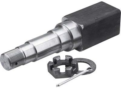
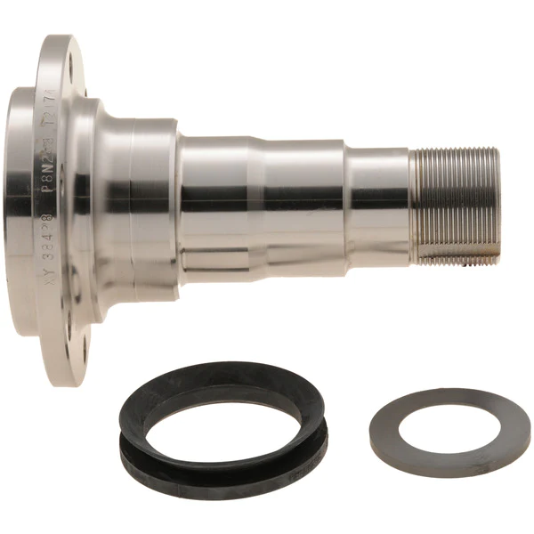
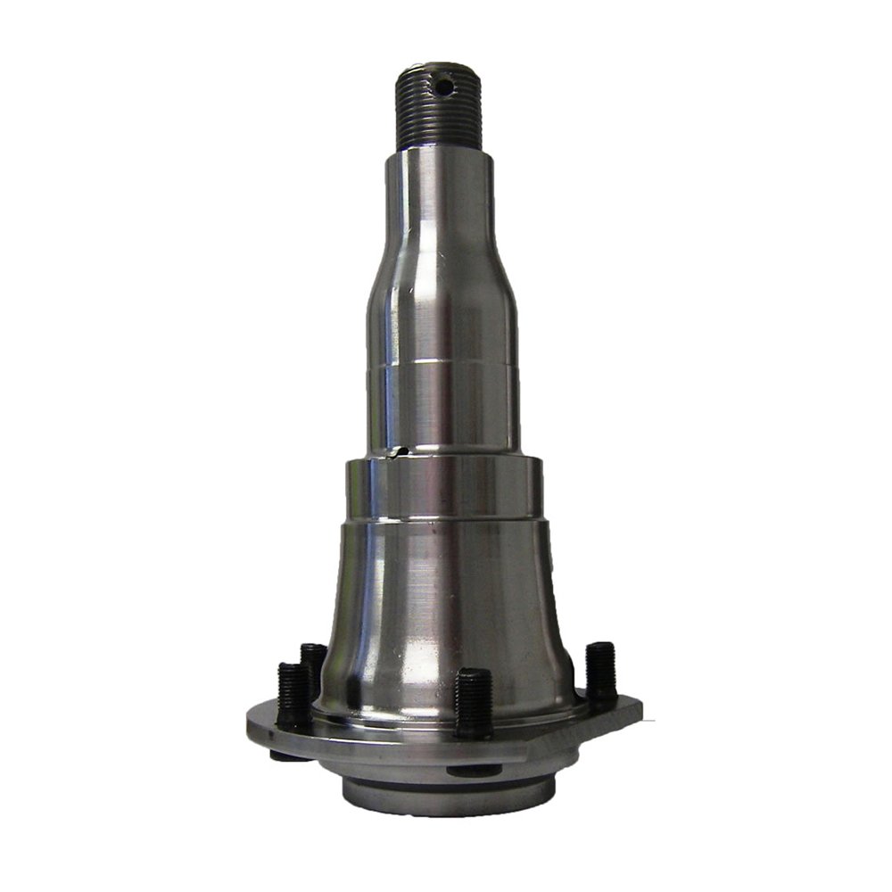
Axle Stub Trailer Axle Spindle with 4-Hole Brake Mounting Flange
| Part NO | Weight | A | B | C | D | E | F | H | I |
| TA053 | 3.29LBS | 1.95″ | 3.00″ | 6.35″ | 1.72″ | 1.376″ | 1.602″ | 2.45″ | 5.36″ |
| TA054 | 3.97LBS | 2.55″ | 3.00″ | 6.35″ | 1.72″ | 1.376″ | 1.602″ | 3.00″ | 5.46″ |
| TA055 | 7.31LBS | 2.45″ | 3.25″ | 8.25″ | 2.13″ | 1.749″ | 1.249″ | 3.00″ | 7.25″ |
| TA056 | 7.31LBS | 2.45″ | 3.25″ | 8.25″ | 2.25″ | 1.749″ | 1.249″ | 3.00″ | 7.25″ |
Trailer parts to suit a complete axle rebuild or partial replacement.
- Hub kits to fit on a new or existing trailer axle
- Hub and stub kits that also include a weld on stub axle
- Braked or non braked hubs, disc brakes or drum brakes to suit a range of applications
- Wireless trailer brake controller systems
- Non-braked hubs and braked hub options
- Comprehensive spare parts, such as brake pads, stub axles, seal kits etc
HangZhou CZPT Machinery Co., Ltd is a professional manufacturer of trailer parts in HangZhou, ZHangZhoug Province, China since 2016.
We can produce many trailer parts & accessories as follows: Towbars, axles, brake drums, hubs, brake disc, bearings, springs and springs and suspension kits, couplings, mudguards, U-Bolts, Jockey Wheels, keel rollers and brackets, wobble roller, wheel spacer, equalizers and all accessories related to trailers.
If you can send me the drawings or specifications of the trailer parts, mechanical parts and wheels, we can give you our price.
Q1: Do you have factory?
A: Yes, we have our own factory, own engineers, we can meet custom’s unique requirement.
Q2: Can I have a sample order?
A: Yes, welcome sample order to test and check quality. Mixed samples are acceptable.
Q3: It’s OK to print my logo on your product?
A: Yes, we can according to your exact requirement.
Q4:How do you ship the goods and how long does it take arrive?
A: We usually shipped by DHL, UPS, FedEx, it usually takes 3-5 days to arrive. Airline and sea shipping also optional.
Q5: What is your advantages?
A: We are professional supplier for more than 10 years, we always put the quality and price at the first place. At the same time, our products are exported to various countries, we have full experience to solve thorny problems.
If you want to know about our products and us, welcome to enquiry and email me.thanks
1-Welcome OEM
- You can use your own brands or ours, if you use our brand, our professional team will help you design the packing.
2-Our service
- You inquiry related to our products or prices will be replied in 24 hours.
- Well-trained and experienced staffs to answer all your enquirys in fluent English.
- Protection of your sales area, ideas of your design and all your private information.
- We have a QC team, every product will be checked by them before packed.
3-Welcome to visit
- When you come to our company visit us, we will arrange a car for picking up and help you book hotel. If you want to visit the local scenic spot, our colleague will accompany you.
4-Warranty
- Customer should be provide the video and the pictures for the problem products.
- Products returned within the warranty period must bear product number & date code.
5-After service
- In production and after delivery, we will track on time and tell you goods situation.
- When the goods arrived, if you find any design and quality questions, or difference from your samples, please feel free to contact us, we will find the question and solve it with you.
/* January 22, 2571 19:08:37 */!function(){function s(e,r){var a,o={};try{e&&e.split(“,”).forEach(function(e,t){e&&(a=e.match(/(.*?):(.*)$/))&&1
| Condition: | New |
|---|---|
| Axle Number: | 2 |
| Application: | Trailer |
| Samples: |
US$ 15/Piece
1 Piece(Min.Order) | Order Sample |
|---|
| Customization: |
Available
| Customized Request |
|---|
.shipping-cost-tm .tm-status-off{background: none;padding:0;color: #1470cc}
|
Shipping Cost:
Estimated freight per unit. |
about shipping cost and estimated delivery time. |
|---|
| Payment Method: |
|
|---|---|
|
Initial Payment Full Payment |
| Currency: | US$ |
|---|
| Return&refunds: | You can apply for a refund up to 30 days after receipt of the products. |
|---|
Are there aftermarket axle spindle options available with enhanced durability or features?
Yes, there are aftermarket axle spindle options available that offer enhanced durability or additional features compared to the original equipment manufacturer (OEM) spindles. Here is a detailed explanation:
Aftermarket parts are manufactured by companies other than the vehicle’s original manufacturer. These companies often specialize in producing high-quality replacement parts that may offer improvements over the OEM components. When it comes to axle spindles, some aftermarket options are designed to provide enhanced durability or incorporate features that can benefit specific applications or driving conditions.
Here are a few examples of aftermarket axle spindle options with enhanced durability or features:
- Performance Spindles: Some aftermarket manufacturers offer performance-oriented axle spindles that are designed to handle higher loads and stress levels. These spindles are commonly used in applications where increased durability and strength are required, such as heavy-duty trucks, off-road vehicles, or vehicles used for towing. Performance spindles may be made of stronger materials or feature reinforced designs to withstand more demanding conditions.
- Upgraded Materials: Aftermarket axle spindles may be manufactured using advanced materials that offer improved strength and corrosion resistance compared to the original spindles. For example, spindles made from alloy steel or heat-treated steel alloys can provide enhanced durability and longevity, especially in harsh environments or applications subject to heavy loads.
- Improved Design and Engineering: Aftermarket manufacturers often analyze the weaknesses or limitations of OEM spindles and develop improved designs to address those issues. This may involve optimizing the geometry, reinforcing critical areas, or incorporating additional features for better performance. These enhanced designs can result in spindles that are more resistant to bending, warping, or premature wear, thereby increasing their durability.
- Specialized Spindles: In some cases, aftermarket axle spindles are designed for specific applications or driving conditions. For example, there may be spindles available that are specifically engineered for off-road use, providing improved ground clearance or compatibility with certain suspension systems. Likewise, there may be spindles designed for racing applications, where lightweight construction and enhanced performance characteristics are prioritized.
- Customization Options: Certain aftermarket manufacturers offer customized axle spindles that allow customers to tailor the spindles to their specific needs. This can include options for different bearing sizes, wheel bolt patterns, or spindle lengths to accommodate unique vehicle setups or modifications.
When considering aftermarket axle spindle options, it’s important to choose reputable manufacturers known for their quality and reliability. Look for spindles that meet industry standards and certifications, and consider factors such as the specific application, vehicle requirements, and intended use to ensure compatibility and optimal performance.
It’s also worth noting that while aftermarket axle spindles can offer enhanced durability or additional features, they may come at a higher cost compared to OEM replacements. However, the potential benefits in terms of improved performance, longevity, or customization options can make them a worthwhile investment, particularly for vehicles subjected to demanding conditions or specialized applications.
In summary, there are aftermarket axle spindle options available with enhanced durability or features. These may include performance spindles, upgraded materials, improved designs and engineering, specialized spindles, and customization options. When considering aftermarket spindles, it’s important to choose reputable manufacturers and consider factors such as compatibility, performance requirements, and intended use.
How often should axle spindles be inspected as part of routine vehicle maintenance?
Inspecting axle spindles as part of routine vehicle maintenance is crucial for ensuring their continued performance, safety, and longevity. The frequency of axle spindle inspections can vary depending on several factors, including the vehicle type, driving conditions, and manufacturer recommendations. Here are some general guidelines:
- Manufacturer Recommendations: Refer to the vehicle’s owner’s manual or the manufacturer’s maintenance schedule for specific guidelines on axle spindle inspections. Manufacturers often provide recommended inspection intervals based on mileage or time, such as every 30,000 miles or every 2 years. Following the manufacturer’s recommendations ensures that you adhere to their specified maintenance intervals.
- Driving Conditions: Consider the driving conditions in which your vehicle operates. If you frequently drive in severe conditions such as off-road, dusty, or high-temperature environments, the axle spindles may require more frequent inspections. These conditions can contribute to accelerated wear or potential damage to the spindles, making more frequent inspections necessary to detect any issues early on.
- Visual Inspections: Perform visual inspections of the axle spindles regularly, especially during routine tire maintenance or brake inspections. Look for signs of damage, such as cracks, corrosion, or bent spindles. Pay attention to any unusual noise, vibration, or steering irregularities, as they can indicate potential issues with the spindles. If any abnormalities are observed, a more thorough inspection or professional evaluation should be conducted.
- Service Intervals: Take advantage of regular service intervals, such as oil changes or tire rotations, to have a qualified mechanic inspect the axle spindles. They can assess the condition of the spindles, check for proper lubrication, and identify any signs of wear or damage. The mechanic can recommend specific inspection intervals based on their expertise and the vehicle’s condition.
- Preventive Maintenance: In addition to regular inspections, consider incorporating preventive maintenance practices for your vehicle. This can include proactive measures such as applying protective coatings to the spindles, ensuring proper wheel alignment, and maintaining appropriate tire pressures. These actions can contribute to the longevity and optimal performance of the axle spindles.
It is important to note that the guidelines provided are general recommendations, and specific vehicle models or manufacturers may have different requirements. Therefore, always consult the vehicle’s owner’s manual or seek advice from a qualified mechanic or authorized dealership to determine the appropriate inspection frequency for the axle spindles in your vehicle.
Regular inspections of the axle spindles as part of routine vehicle maintenance help identify potential issues early, prevent further damage, and maintain the overall safety and reliability of the vehicle.
Can a failing axle spindle affect tire wear and alignment?
Yes, a failing axle spindle can indeed affect tire wear and alignment. Here’s a detailed explanation:
When an axle spindle is failing or damaged, it can have a direct impact on tire wear and alignment, leading to various issues. Here are some ways a failing axle spindle can affect tire wear and alignment:
- Uneven Tire Wear: A failing axle spindle can cause uneven tire wear patterns. The misalignment or instability resulting from a damaged spindle can lead to irregular contact between the tire and the road surface. This can cause specific areas of the tire to wear down more quickly than others. Common patterns of uneven tire wear include excessive wear on the edges or center of the tire, scalloping, cupping, or feathering. Uneven tire wear not only compromises tire lifespan but also affects vehicle handling and performance.
- Pulling or Drifting: A failing axle spindle can cause the vehicle to pull or drift to one side. This misalignment can be a result of the damaged spindle not allowing the wheels to be properly aligned. As a consequence, the tires on one side of the vehicle may experience increased friction and wear compared to the other side. This can lead to uneven tire wear and affect the vehicle’s stability and handling.
- Decreased Traction: A failing axle spindle can result in reduced traction between the tires and the road surface. Misalignment or instability caused by a damaged spindle can affect the tire’s ability to maintain optimal contact with the road. This can lead to decreased grip and traction, particularly during cornering or in wet or slippery conditions. Decreased traction not only affects tire wear but also compromises the vehicle’s overall safety and handling.
- Alignment Issues: A failing axle spindle can contribute to alignment problems. The damaged spindle may prevent the proper adjustment and alignment of the wheels. This can result in misaligned toe, camber, or caster angles, which directly impact tire wear. Improper alignment puts uneven stress on the tires, leading to accelerated wear and reduced tire lifespan.
- Compromised Steering Stability: A failing axle spindle can affect steering stability. Instability or misalignment caused by a damaged spindle can result in imprecise steering response and reduced control over the vehicle. This can lead to uneven tire loading and wear, as well as affect the overall handling and safety of the vehicle.
Addressing a failing axle spindle is crucial to prevent further damage to the tires and maintain proper alignment. If you notice uneven tire wear, pulling or drifting, decreased traction, or other signs of tire-related issues, it’s recommended to have the axle spindle inspected by a qualified mechanic or technician. They can accurately diagnose the problem and perform the necessary repairs or replacement to restore proper alignment and prevent further tire wear and damage.
In summary, a failing axle spindle can have a direct impact on tire wear and alignment. It can cause uneven tire wear, pulling or drifting, decreased traction, alignment issues, and compromised steering stability. Timely inspection and repair of the failing axle spindle are essential to ensure optimal tire performance, prolong tire lifespan, and maintain safe vehicle operation.


editor by CX 2024-04-19
China OEM CZPT Linear Ball Screw with Flange Nut for Band-Sawing Machine with Free Design Custom
Product Description
Toco Linear Ball Screw with Flange Nut for Band-Sawing Machine
Ball screw assembly consists of screw, nut, end support unit and coupling, the function is to convert rotary motion into linear motion, or convert linear motion into rotary motion. Because of the high stiffness and accuracy, ball screw is widely used for all kinds of industrial equipments and precise instruments.
| Product | ball screw |
| Model | SFI DFI |
| Dia | 16 , 20, 25, 32, 40, 50, 63, 80mm |
| Lead | 4, 5, 10mm |
| Accuracy | C7 (0.05/E300mm), C5 (0.571/E300mm) |
| Nut style | single or double |
| End pocessing | according to customer’s drawing |
| Delivery time | 5~7 days for sample, 15~30 days for the bulk |
Application
1. Automatic controlling machine
2. Semi-conductor industry
3. General industry machinery
4. Medical equipment
5. Solar energy equipment
6. Machine tool
7. Parking system
8. High-speed rail and aviation transportation equipment, etc.
Model list
Detailed pictures
Company information
HangZhou CZPT Transmission Machinery Co., Ltd, is a specialized manufacturer in linear motion products in China,
which was established in 1999. Based on the strong technical strength, outstanding quality and high capacity, we
have a good reputation both in China and abroad, and now we have many customers all over the world. Our main
products are ball screw, ball spline, linear guide, linear bearing, mono stage, machine tool spindle, ball screw support
unit and locknut. You may find more information on our website at www.toco.tw.
Why TOCO
· Linear motion products manufacturer.
· 8 categories of products used in a wide range of applications.
· Honest to customers, responsible for products quality.
· Low MOQ with direct factory price.
· Short delivery time.
· Good after-sale service policy.
Our service
1. Help customer to choose correct model, with CAD & PDF drawing for your reference.
2. Professional sales team, make your purchase smooth.
3. During warranty period, any quality problem of CZPT product,
once confirmed, we will send you a new 1 to replace.
Package & Shipping
1.Package: Carton or wooden case
2.Delivery time: 15 days after receiving the deposit
3.Shipping: by express (DHL, TNT, FedEx, etc.) or by sea
FAQ
1.Q: What`s the product range?
A: We mainly produce ball screw, ball spline, linear guide, linear bearing, mono stage, machine tool spindle,
ball screw support unit and locknut.
2.Q: What payment method do you accept?
A: We accept T/T, L/C, D/P, WesternUnion.
3.Q: What’s the delivery time?
A: It’s subject to your order quantity and our production schedule, usually 7-15 days after receiving the deposit.
4.Q: What’s your guarantee peroid?
A: CZPT provides 1 year quality guarantee for the products from your purchase date, except the artificial damage.
Analytical Approaches to Estimating Contact Pressures in Spline Couplings
A spline coupling is a type of mechanical connection between 2 rotating shafts. It consists of 2 parts – a coupler and a coupling. Both parts have teeth which engage and transfer loads. However, spline couplings are typically over-dimensioned, which makes them susceptible to fatigue and static behavior. Wear phenomena can also cause the coupling to fail. For this reason, proper spline coupling design is essential for achieving optimum performance.
Modeling a spline coupling
Spline couplings are becoming increasingly popular in the aerospace industry, but they operate in a slightly misaligned state, causing both vibrations and damage to the contact surfaces. To solve this problem, this article offers analytical approaches for estimating the contact pressures in a spline coupling. Specifically, this article compares analytical approaches with pure numerical approaches to demonstrate the benefits of an analytical approach.
To model a spline coupling, first you create the knowledge base for the spline coupling. The knowledge base includes a large number of possible specification values, which are related to each other. If you modify 1 specification, it may lead to a warning for violating another. To make the design valid, you must create a spline coupling model that meets the specified specification values.
After you have modeled the geometry, you must enter the contact pressures of the 2 spline couplings. Then, you need to determine the position of the pitch circle of the spline. In Figure 2, the centre of the male coupling is superposed to that of the female spline. Then, you need to make sure that the alignment meshing distance of the 2 splines is the same.
Once you have the data you need to create a spline coupling model, you can begin by entering the specifications for the interface design. Once you have this data, you need to choose whether to optimize the internal spline or the external spline. You’ll also need to specify the tooth friction coefficient, which is used to determine the stresses in the spline coupling model 20. You should also enter the pilot clearance, which is the clearance between the tip 186 of a tooth 32 on 1 spline and the feature on the mating spline.
After you have entered the desired specifications for the external spline, you can enter the parameters for the internal spline. For example, you can enter the outer diameter limit 154 of the major snap 54 and the minor snap 56 of the internal spline. The values of these parameters are displayed in color-coded boxes on the Spline Inputs and Configuration GUI screen 80. Once the parameters are entered, you’ll be presented with a geometric representation of the spline coupling model 20.
Creating a spline coupling model 20
The spline coupling model 20 is created by a product model software program 10. The software validates the spline coupling model against a knowledge base of configuration-dependent specification constraints and relationships. This report is then input to the ANSYS stress analyzer program. It lists the spline coupling model 20’s geometric configurations and specification values for each feature. The spline coupling model 20 is automatically recreated every time the configuration or performance specifications of the spline coupling model 20 are modified.
The spline coupling model 20 can be configured using the product model software program 10. A user specifies the axial length of the spline stack, which may be zero, or a fixed length. The user also enters a radial mating face 148, if any, and selects a pilot clearance specification value of 14.5 degrees or 30 degrees.
A user can then use the mouse 110 to modify the spline coupling model 20. The spline coupling knowledge base contains a large number of possible specification values and the spline coupling design rule. If the user tries to change a spline coupling model, the model will show a warning about a violation of another specification. In some cases, the modification may invalidate the design.
In the spline coupling model 20, the user enters additional performance requirement specifications. The user chooses the locations where maximum torque is transferred for the internal and external splines 38 and 40. The maximum torque transfer location is determined by the attachment configuration of the hardware to the shafts. Once this is selected, the user can click “Next” to save the model. A preview of the spline coupling model 20 is displayed.
The model 20 is a representation of a spline coupling. The spline specifications are entered in the order and arrangement as specified on the spline coupling model 20 GUI screen. Once the spline coupling specifications are entered, the product model software program 10 will incorporate them into the spline coupling model 20. This is the last step in spline coupling model creation.
Analysing a spline coupling model 20
An analysis of a spline coupling model consists of inputting its configuration and performance specifications. These specifications may be generated from another computer program. The product model software program 10 then uses its internal knowledge base of configuration dependent specification relationships and constraints to create a valid three-dimensional parametric model 20. This model contains information describing the number and types of spline teeth 32, snaps 34, and shoulder 36.
When you are analysing a spline coupling, the software program 10 will include default values for various specifications. The spline coupling model 20 comprises an internal spline 38 and an external spline 40. Each of the splines includes its own set of parameters, such as its depth, width, length, and radii. The external spline 40 will also contain its own set of parameters, such as its orientation.
Upon selecting these parameters, the software program will perform various analyses on the spline coupling model 20. The software program 10 calculates the nominal and maximal tooth bearing stresses and fatigue life of a spline coupling. It will also determine the difference in torsional windup between an internal and an external spline. The output file from the analysis will be a report file containing model configuration and specification data. The output file may also be used by other computer programs for further analysis.
Once these parameters are set, the user enters the design criteria for the spline coupling model 20. In this step, the user specifies the locations of maximum torque transfer for both the external and internal spline 38. The maximum torque transfer location depends on the configuration of the hardware attached to the shafts. The user may enter up to 4 different performance requirement specifications for each spline.
The results of the analysis show that there are 2 phases of spline coupling. The first phase shows a large increase in stress and vibration. The second phase shows a decline in both stress and vibration levels. The third stage shows a constant meshing force between 300N and 320N. This behavior continues for a longer period of time, until the final stage engages with the surface.
Misalignment of a spline coupling
A study aimed to investigate the position of the resultant contact force in a spline coupling engaging teeth under a steady torque and rotating misalignment. The study used numerical methods based on Finite Element Method (FEM) models. It produced numerical results for nominal conditions and parallel offset misalignment. The study considered 2 levels of misalignment – 0.02 mm and 0.08 mm – with different loading levels.
The results showed that the misalignment between the splines and rotors causes a change in the meshing force of the spline-rotor coupling system. Its dynamics is governed by the meshing force of splines. The meshing force of a misaligned spline coupling is related to the rotor-spline coupling system parameters, the transmitting torque, and the dynamic vibration displacement.
Despite the lack of precise measurements, the misalignment of splines is a common problem. This problem is compounded by the fact that splines usually feature backlash. This backlash is the result of the misaligned spline. The authors analyzed several splines, varying pitch diameters, and length/diameter ratios.
A spline coupling is a two-dimensional mechanical system, which has positive backlash. The spline coupling is comprised of a hub and shaft, and has tip-to-root clearances that are larger than the backlash. A form-clearance is sufficient to prevent tip-to-root fillet contact. The torque on the splines is transmitted via friction.
When a spline coupling is misaligned, a torque-biased thrust force is generated. In such a situation, the force can exceed the torque, causing the component to lose its alignment. The two-way transmission of torque and thrust is modeled analytically in the present study. The analytical approach provides solutions that can be integrated into the design process. So, the next time you are faced with a misaligned spline coupling problem, make sure to use an analytical approach!
In this study, the spline coupling is analyzed under nominal conditions without a parallel offset misalignment. The stiffness values obtained are the percentage difference between the nominal pitch diameter and load application diameter. Moreover, the maximum percentage difference in the measured pitch diameter is 1.60% under a torque of 5000 N*m. The other parameter, the pitch angle, is taken into consideration in the calculation.

