Product Description
Product Description
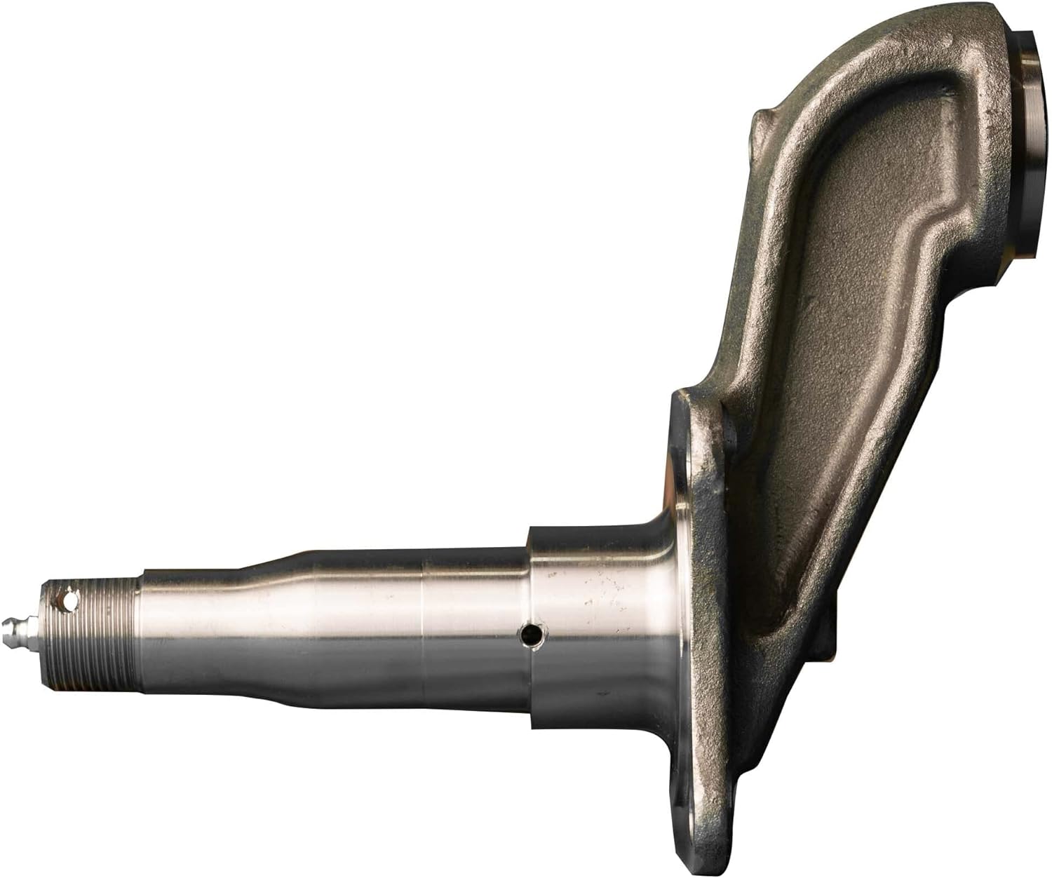
King Steel can machine and manufacture wind turbine main shafts for customers. We can specialize in the production of wind turbine shafts of different specifications.
We can provide wind turbine main shafts of various materials, such as ZG430640 cast steel, 60#, 65#, 65Mn, 42CrMoA or according to your requirements.
The wind turbine shafts we produce can meet most international standards, such as ASTM, ASME, DIN, JIS, ISO, BS, API, EN.
Specification:
Material: 34CrNiMo6, 42CrMo4
Weight: about 15t
Production capacity: 0.75MW-3MW
Maximum weight: 23T
Craft: Forging and Casting
Usage: used for wind power generation
Inspection: During each process and after the product is finally manufactured, all items are thoroughly inspected and tested to ensure the highest quality products are put on the market.
|
Product |
wind turbine main shaft |
|
Materials |
carbon steel,alloy steel, stainless steel, according to drawing. |
|
Standard |
ASTM, AISI, ASME, DIN, EN, AS, GB. |
|
Processing range |
outer diameter Max1400mm, length Max18000mm. |
|
Main processes |
forging, heat treatment, machining |
|
Main tests |
chemical composition, mechanical properties, PT, UT, MT, hardness, size, roughness. |
|
Major exporting countries |
Australia, the United States, Italy, Germany, Finland, Norway, Thailand, India, etc. |
|
Application |
Wind turbine |
Manufacturing process:
Rraw matrial — Forging testing– Turning — Drilling — Heat Treatment — Milling– Grinding — Shaping and hobbing Process — Packing — Shipping.
After Sales Service
1. OEM and customized service.
2. Full machining, primer coating, surface treatment.
3. Complete material testing process.
4. Quality control
Contact us
Please contact us for more information and quotations.
/* January 22, 2571 19:08:37 */!function(){function s(e,r){var a,o={};try{e&&e.split(“,”).forEach(function(e,t){e&&(a=e.match(/(.*?):(.*)$/))&&1
| Material: | Alloy Steel |
|---|---|
| Load: | Central Spindle |
| Stiffness & Flexibility: | Stiffness / Rigid Axle |
| Customization: |
Available
| Customized Request |
|---|
.shipping-cost-tm .tm-status-off{background: none;padding:0;color: #1470cc}
|
Shipping Cost:
Estimated freight per unit. |
about shipping cost and estimated delivery time. |
|---|
| Payment Method: |
|
|---|---|
|
Initial Payment Full Payment |
| Currency: | US$ |
|---|
| Return&refunds: | You can apply for a refund up to 30 days after receipt of the products. |
|---|
Where can I find reliable resources for learning about axle spindle maintenance and repair?
If you’re looking to learn about axle spindle maintenance and repair, there are several reliable resources available to help you gain the necessary knowledge and skills. Here’s a detailed explanation of where you can find such resources:
- Vehicle Manufacturer’s Official Documentation: One of the best sources of information for axle spindle maintenance and repair is the official documentation provided by the vehicle manufacturer. This includes the vehicle’s owner’s manual, service manual, or technical guides. These resources often contain detailed instructions, diagrams, torque specifications, and other relevant information specific to your vehicle make, model, and year.
- Automotive Repair Manuals: There are various reputable automotive repair manuals available in the market. These manuals, such as those published by Haynes or Chilton, provide comprehensive guides for vehicle maintenance and repair. They often cover a wide range of topics, including axle spindle maintenance and repair, with step-by-step instructions, illustrations, and troubleshooting tips.
- Online Repair Guides and Websites: The internet offers a wealth of information on automotive maintenance and repair. Websites such as AutoZone, RepairPal, and iFixit provide detailed repair guides, tutorials, and forums where you can find information specific to axle spindle maintenance and repair. Additionally, online forums and communities dedicated to automotive enthusiasts can be valuable resources for learning from experienced individuals and seeking advice.
- YouTube Video Tutorials: YouTube is a popular platform for instructional videos, and you can find numerous video tutorials related to axle spindle maintenance and repair. Many automotive enthusiasts, mechanics, and professional technicians create informative videos demonstrating the procedures, tools, and techniques involved in working on axle spindles. These videos often provide visual demonstrations that can be helpful for understanding the repair process.
- Local Libraries and Bookstores: Your local library or bookstore may have a selection of automotive repair books and manuals that cover axle spindle maintenance and repair. These resources can be valuable references for learning about the topic in a more comprehensive and in-depth manner.
- Professional Mechanics and Technicians: If you have access to professional mechanics or technicians, they can be excellent resources for learning about axle spindle maintenance and repair. They possess hands-on experience and expert knowledge in the field. You can seek their guidance, ask questions, and even observe them during the repair process to gain practical insights and tips.
When utilizing these resources, it’s important to cross-reference information and ensure that you’re consulting reputable sources. Always prioritize information from reliable and trusted sources, such as official documentation, reputable repair manuals, and established automotive websites or experts.
Learning about axle spindle maintenance and repair requires a combination of theoretical knowledge and practical experience. It’s recommended to start with the basics, familiarize yourself with the terminology, and gradually progress to more advanced topics. Take your time, follow safety precautions, and be prepared to seek professional assistance when necessary.
In summary, reliable resources for learning about axle spindle maintenance and repair can be found in various forms, including vehicle manufacturer’s official documentation, automotive repair manuals, online repair guides and websites, YouTube video tutorials, local libraries and bookstores, and professional mechanics and technicians. By utilizing these resources, you can enhance your understanding and skills in maintaining and repairing axle spindles effectively.
Can changes in the vehicle’s ride height impact the angles and performance of axle spindles?
Yes, changes in the vehicle’s ride height can indeed impact the angles and performance of axle spindles. Here is a detailed explanation:
The ride height of a vehicle refers to the distance between the ground and the chassis or body of the vehicle. It is determined by several factors, including the suspension system, springs, shocks, and overall design. Altering the ride height, either by raising or lowering the vehicle, can have various effects on the angles and performance of the axle spindles.
Here are some ways in which changes in ride height can impact the axle spindles:
- Steering Geometry: The angles and geometry of the steering system are closely linked to the ride height of the vehicle. When the ride height is modified, it can affect the steering angles, such as the caster, camber, and toe. These angles determine how the wheels interact with the road surface and influence the handling, stability, and tire wear. Any alteration to the steering geometry can indirectly impact the axle spindles and their performance.
- Axle Alignment: Changes in ride height can also affect the alignment of the axles. Raising or lowering the vehicle can lead to changes in the relative position and alignment of the front and rear axles. This can introduce changes in the suspension geometry, including the axle angles, which in turn can affect the load distribution, tire contact patch, and overall performance of the axle spindles.
- Components Interference: In some cases, significant changes in ride height can lead to interference issues between suspension components and other parts of the vehicle. For example, lowering the vehicle excessively can cause the axle spindles or other suspension elements to come into contact with the body, frame, or other nearby components. This can result in limited suspension travel, reduced performance, or potential damage to the axle spindles.
- Suspension Travel and Dynamics: Altering the ride height can affect the suspension travel and dynamics of the vehicle. Lowering the ride height typically reduces the suspension’s range of motion, which can impact the ability of the axle spindles to absorb bumps, maintain tire contact with the road, and provide adequate suspension travel. Conversely, raising the ride height can increase the suspension travel but may also affect the vehicle’s center of gravity and stability.
- Ground Clearance: Changes in ride height can impact the vehicle’s ground clearance, which is the distance between the lowest point of the vehicle and the ground. Lowering the ride height reduces ground clearance, potentially increasing the risk of the axle spindles or other undercarriage components scraping or hitting obstacles on the road. This can lead to damage or premature wear of the axle spindles if they come into contact with road hazards.
It’s worth noting that modifying the ride height of a vehicle, particularly beyond the manufacturer’s specifications, can have implications on various aspects of vehicle performance, including the axle spindles. Therefore, it’s important to consider these factors and exercise caution when making ride height adjustments.
If you are considering changing the ride height of your vehicle, it is recommended to consult with knowledgeable professionals or experienced enthusiasts who are familiar with the specific vehicle model and its suspension system. They can provide guidance on appropriate modifications, potential impacts on the axle spindles, and the overall performance and safety of the vehicle.
In summary, changes in a vehicle’s ride height can impact the angles and performance of axle spindles. These changes can affect steering geometry, axle alignment, component interference, suspension travel and dynamics, as well as ground clearance. It’s important to consider these factors and seek expert advice when modifying the ride height to ensure optimal performance and safety of the axle spindles and the vehicle as a whole.
Can a failing axle spindle affect tire wear and alignment?
Yes, a failing axle spindle can indeed affect tire wear and alignment. Here’s a detailed explanation:
When an axle spindle is failing or damaged, it can have a direct impact on tire wear and alignment, leading to various issues. Here are some ways a failing axle spindle can affect tire wear and alignment:
- Uneven Tire Wear: A failing axle spindle can cause uneven tire wear patterns. The misalignment or instability resulting from a damaged spindle can lead to irregular contact between the tire and the road surface. This can cause specific areas of the tire to wear down more quickly than others. Common patterns of uneven tire wear include excessive wear on the edges or center of the tire, scalloping, cupping, or feathering. Uneven tire wear not only compromises tire lifespan but also affects vehicle handling and performance.
- Pulling or Drifting: A failing axle spindle can cause the vehicle to pull or drift to one side. This misalignment can be a result of the damaged spindle not allowing the wheels to be properly aligned. As a consequence, the tires on one side of the vehicle may experience increased friction and wear compared to the other side. This can lead to uneven tire wear and affect the vehicle’s stability and handling.
- Decreased Traction: A failing axle spindle can result in reduced traction between the tires and the road surface. Misalignment or instability caused by a damaged spindle can affect the tire’s ability to maintain optimal contact with the road. This can lead to decreased grip and traction, particularly during cornering or in wet or slippery conditions. Decreased traction not only affects tire wear but also compromises the vehicle’s overall safety and handling.
- Alignment Issues: A failing axle spindle can contribute to alignment problems. The damaged spindle may prevent the proper adjustment and alignment of the wheels. This can result in misaligned toe, camber, or caster angles, which directly impact tire wear. Improper alignment puts uneven stress on the tires, leading to accelerated wear and reduced tire lifespan.
- Compromised Steering Stability: A failing axle spindle can affect steering stability. Instability or misalignment caused by a damaged spindle can result in imprecise steering response and reduced control over the vehicle. This can lead to uneven tire loading and wear, as well as affect the overall handling and safety of the vehicle.
Addressing a failing axle spindle is crucial to prevent further damage to the tires and maintain proper alignment. If you notice uneven tire wear, pulling or drifting, decreased traction, or other signs of tire-related issues, it’s recommended to have the axle spindle inspected by a qualified mechanic or technician. They can accurately diagnose the problem and perform the necessary repairs or replacement to restore proper alignment and prevent further tire wear and damage.
In summary, a failing axle spindle can have a direct impact on tire wear and alignment. It can cause uneven tire wear, pulling or drifting, decreased traction, alignment issues, and compromised steering stability. Timely inspection and repair of the failing axle spindle are essential to ensure optimal tire performance, prolong tire lifespan, and maintain safe vehicle operation.


editor by CX 2024-04-08
China Best Sales 4crnimo6 Large Wind Power Shaft 36CrNiMo4 Wind Power Generator Spindle axle car part
Product Description
Product Description
King Steel can machine and manufacture wind turbine main shafts for customers. We can specialize in the production of wind turbine shafts of different specifications.
We can provide wind turbine main shafts of various materials, such as ZG430640 cast steel, 60#, 65#, 65Mn, 42CrMoA or according to your requirements.
The wind turbine shafts we produce can meet most international standards, such as ASTM, ASME, DIN, JIS, ISO, BS, API, EN.
Specification:
Material: 34CrNiMo6, 42CrMo4
Weight: about 15t
Production capacity: 0.75MW-3MW
Maximum weight: 23T
Craft: Forging and Casting
Usage: used for wind power generation
Inspection: During each process and after the product is finally manufactured, all items are thoroughly inspected and tested to ensure the highest quality products are put on the market.
|
Product |
wind turbine main shaft |
|
Materials |
carbon steel,alloy steel, stainless steel, according to drawing. |
|
Standard |
ASTM, AISI, ASME, DIN, EN, AS, GB. |
|
Processing range |
outer diameter Max1400mm, length Max18000mm. |
|
Main processes |
forging, heat treatment, machining |
|
Main tests |
chemical composition, mechanical properties, PT, UT, MT, hardness, size, roughness. |
|
Major exporting countries |
Australia, the United States, Italy, Germany, Finland, Norway, Thailand, India, etc. |
|
Application |
Wind turbine |
Manufacturing process:
Rraw matrial — Forging testing– Turning — Drilling — Heat Treatment — Milling– Grinding — Shaping and hobbing Process — Packing — Shipping.
After Sales Service
1. OEM and customized service.
2. Full machining, primer coating, surface treatment.
3. Complete material testing process.
4. Quality control
Contact us
Please contact us for more information and quotations.
/* March 10, 2571 17:59:20 */!function(){function s(e,r){var a,o={};try{e&&e.split(“,”).forEach(function(e,t){e&&(a=e.match(/(.*?):(.*)$/))&&1
| Material: | Alloy Steel |
|---|---|
| Load: | Central Spindle |
| Stiffness & Flexibility: | Stiffness / Rigid Axle |
| Customization: |
Available
| Customized Request |
|---|
.shipping-cost-tm .tm-status-off{background: none;padding:0;color: #1470cc}
|
Shipping Cost:
Estimated freight per unit. |
about shipping cost and estimated delivery time. |
|---|
| Payment Method: |
|
|---|---|
|
Initial Payment Full Payment |
| Currency: | US$ |
|---|
| Return&refunds: | You can apply for a refund up to 30 days after receipt of the products. |
|---|
Are there specific tools required for removing and installing an axle spindle assembly?
Yes, removing and installing an axle spindle assembly typically requires specific tools to ensure the task is performed correctly and efficiently. Here’s a detailed explanation of some of the tools commonly used for this job:
- Hydraulic Jack and Jack Stands: These tools are used to safely lift and support the vehicle off the ground, providing access to the axle spindle assembly. A hydraulic jack is used to raise the vehicle, while jack stands are placed under the chassis to secure it at the desired height.
- Socket Set and Wrenches: A socket set with various socket sizes and wrenches is essential for loosening and tightening the fasteners that secure the axle spindle assembly and its associated components. These tools enable you to remove nuts, bolts, and other fasteners during disassembly and reinstall them during assembly.
- Pry Bar or Ball Joint Separator: A pry bar or a ball joint separator may be needed to separate ball joints, tie rod ends, or other connections that are attached to the axle spindle. These tools help to release the components without damaging them or the spindle assembly.
- Torque Wrench: To ensure proper torque specifications are met during assembly, a torque wrench is essential. It allows you to apply the correct amount of torque to the fasteners, ensuring they are neither too loose nor too tight. Over- or under-tightening can lead to component failure or damage.
- Axle Nut Socket: In some cases, a specialized socket known as an axle nut socket is required to remove and install the axle nut that secures the axle shaft to the wheel hub. This socket is designed to fit the specific size and shape of the axle nut, allowing for proper engagement and torque application.
- Bearing Puller or Press: Depending on the design of the wheel bearing assembly, a bearing puller or press may be necessary to remove the old bearing from the axle spindle or to install a new bearing. These tools ensure controlled and precise removal or installation of the bearing, minimizing the risk of damage to the spindle or the new bearing.
- Brake Tools: If the axle spindle is associated with the brake system, you may need specific brake tools such as a caliper piston tool, brake pad spreader, or brake bleeder kit to properly disassemble and reassemble the brake components during the axle spindle replacement.
- Shop Manual or Repair Guide: While not a physical tool, having access to the vehicle’s shop manual or a reliable repair guide is crucial. These resources provide step-by-step instructions, torque specifications, and other essential information specific to your vehicle make, model, and year.
It’s important to note that the specific tools required for removing and installing an axle spindle assembly can vary depending on the vehicle’s make, model, and design. Additionally, certain specialized tools may be needed for specific axle spindle configurations or unique components associated with the assembly.
Before attempting to replace an axle spindle assembly, it’s strongly recommended to consult the vehicle’s shop manual or a trusted repair guide to identify the specific tools required and to understand the proper procedures for your particular vehicle. If you lack the necessary tools or experience, it is advisable to seek assistance from a professional mechanic or technician who has the expertise and appropriate tools for the job.
In summary, specific tools are typically required for removing and installing an axle spindle assembly. These tools include a hydraulic jack, jack stands, socket set, wrenches, pry bar, torque wrench, axle nut socket, bearing puller or press, brake tools (if applicable), and access to a shop manual or repair guide. Utilizing the correct tools ensures that the job is performed safely and accurately.

How often should axle spindles be inspected as part of routine vehicle maintenance?
Inspecting axle spindles as part of routine vehicle maintenance is crucial for ensuring their continued performance, safety, and longevity. The frequency of axle spindle inspections can vary depending on several factors, including the vehicle type, driving conditions, and manufacturer recommendations. Here are some general guidelines:
- Manufacturer Recommendations: Refer to the vehicle’s owner’s manual or the manufacturer’s maintenance schedule for specific guidelines on axle spindle inspections. Manufacturers often provide recommended inspection intervals based on mileage or time, such as every 30,000 miles or every 2 years. Following the manufacturer’s recommendations ensures that you adhere to their specified maintenance intervals.
- Driving Conditions: Consider the driving conditions in which your vehicle operates. If you frequently drive in severe conditions such as off-road, dusty, or high-temperature environments, the axle spindles may require more frequent inspections. These conditions can contribute to accelerated wear or potential damage to the spindles, making more frequent inspections necessary to detect any issues early on.
- Visual Inspections: Perform visual inspections of the axle spindles regularly, especially during routine tire maintenance or brake inspections. Look for signs of damage, such as cracks, corrosion, or bent spindles. Pay attention to any unusual noise, vibration, or steering irregularities, as they can indicate potential issues with the spindles. If any abnormalities are observed, a more thorough inspection or professional evaluation should be conducted.
- Service Intervals: Take advantage of regular service intervals, such as oil changes or tire rotations, to have a qualified mechanic inspect the axle spindles. They can assess the condition of the spindles, check for proper lubrication, and identify any signs of wear or damage. The mechanic can recommend specific inspection intervals based on their expertise and the vehicle’s condition.
- Preventive Maintenance: In addition to regular inspections, consider incorporating preventive maintenance practices for your vehicle. This can include proactive measures such as applying protective coatings to the spindles, ensuring proper wheel alignment, and maintaining appropriate tire pressures. These actions can contribute to the longevity and optimal performance of the axle spindles.
It is important to note that the guidelines provided are general recommendations, and specific vehicle models or manufacturers may have different requirements. Therefore, always consult the vehicle’s owner’s manual or seek advice from a qualified mechanic or authorized dealership to determine the appropriate inspection frequency for the axle spindles in your vehicle.
Regular inspections of the axle spindles as part of routine vehicle maintenance help identify potential issues early, prevent further damage, and maintain the overall safety and reliability of the vehicle.
What is the primary role of the axle spindle in a vehicle’s suspension system?
The primary role of the axle spindle in a vehicle’s suspension system is to support and facilitate the rotation of the wheel assembly. Here’s a detailed explanation:
The axle spindle, also known as the wheel spindle or stub axle, is a component of the suspension system that connects the wheel hub assembly to the suspension system. It plays a crucial role in supporting the weight of the vehicle, transmitting driving forces, and allowing the wheel assembly to rotate smoothly.
Here are the primary functions and roles of the axle spindle:
- Wheel Mounting: The axle spindle provides a mounting point for the wheel hub assembly. It typically extends from the steering knuckle or axle beam and incorporates a flange or hub surface where the wheel is mounted. The spindle ensures proper alignment and secure attachment of the wheel to the suspension system.
- Load Support: One of the main responsibilities of the axle spindle is to support the weight of the vehicle and any additional loads. It transfers the vertical load from the wheel assembly to the suspension system and ultimately to the vehicle chassis. The spindle should be designed to withstand the weight and forces encountered during normal driving conditions.
- Wheel Rotation: The axle spindle allows the wheel assembly to rotate freely. It acts as an axle or pivot point around which the wheel rotates when the vehicle is in motion. The spindle is typically designed with a smooth, cylindrical shape that fits into the wheel bearings, allowing for low-friction rotation.
- Steering Function: In some suspension systems, particularly those with steering knuckles, the axle spindle also plays a role in the steering function. It connects to the steering linkage or tie rods, allowing for the controlled movement of the wheel assembly during steering maneuvers. The spindle’s design and attachment points should facilitate the proper functioning of the steering system.
- Transmission of Forces: The axle spindle transmits driving and braking forces from the wheel assembly to the suspension system. These forces include torque from the engine during acceleration and braking forces when the brakes are applied. The spindle should be able to handle these forces without failure or excessive deflection.
It’s important to note that the design and construction of axle spindles can vary depending on the specific suspension system used in a vehicle. Different suspension types, such as independent suspension or solid axle suspension, may have variations in spindle design and attachment methods. Additionally, the axle spindle must be properly lubricated and maintained to ensure smooth operation and longevity.
In summary, the primary role of the axle spindle in a vehicle’s suspension system is to support and facilitate the rotation of the wheel assembly. It provides a mounting point for the wheel hub assembly, supports the vehicle’s weight, allows for wheel rotation, contributes to the steering function, and transmits driving forces. The design and construction of the axle spindle may vary depending on the suspension system used in the vehicle.
editor by CX 2024-02-06
China wholesaler Make on Demand Cardan Shaft for Wind Power Equipment near me supplier
Product Description
1.;Who we are?
HangZhou XIHU (WEST LAKE) DIS. CARDANSHAFT CO;LTD has 15 years history.;When the general manager Mr.;Rony Du graduated from the university,;he always concentrated his attention on the research and development,;production and sales of the cardan shaft.;Mr.;Rony Du and his team started from scratch,;from 1 lathe and a very small order,;step by step to grow up.;He often said to his team”We will only do 1 thing well——to make the perfect cardan shaft”.;
HangZhou XIHU (WEST LAKE) DIS. CARDANSHAFT CO.;,;LTD was founded in 2005.;The registered capital is 8 million ,;covers an area of 15 acres,; has 30 existing staff.; The company specializing in the production of SWC,; SWP cross universal coupling and drum tooth coupling.;The company with factory is located in the beautiful coast of Tai Lake –Hudai (HangZhou Economic Development Zone Hudai Industrial Park);.;
In order to become China’s leading cardan shaft one-stop solution expert supplier .;XIHU (WEST LAKE) DIS. CARDANSHAFT independent research and development of SWC light,; medium,; short,; heavy Designs cardan shaft have reached the leading domestic level.;Products not only supporting domestic large and medium-sized customers,; but also exported to the United States,; India,; Vietnam,; Laos,; Ukraine,; Russia,; Germany,; Britain and other countries and areas.;In the past 15 years,; the company has accumulated a wealth of experience,; learn from foreign advanced technology,; and to absorb and use the universal axis has been improved several times,; so that the structure is maturing,; significantly improved performance.;
XIHU (WEST LAKE) DIS. belief:; “Continuous innovation,; optimize the structure,; perseverance” to create a high quality of outstanding cardan shaft manufacturer.;We always adhere to the ISO9001 quality control system,; from the details to start,; standardize the production process,; and to achieve processing equipment “specialization,; numerical control” rapid increase in product quality.;This Not only won the majority of customers reputation,; but also access to peer recognition.; We continue to strive to pursue:; “for customers to create the greatest value,; for the staff to build the best platform”,; will be CZPT to achieve customer and business mutually beneficial CZPT situation.;
2.;Why choose us?
First,;select raw material carefully
The cross is the core component of cardan shaft,;so the selection of material is particularly critical.;Raw materials of the cross for light Duty Size and Medium Duty Size,;we choose the 20CrMnTi special gear steel bar from SHAGANG GROUP.;Being forged in 2500 ton friction press to ensure internal metallurgical structure,;inspecting the geometric dimensions of each part to meet the drawing requirements,;then transfer to machining,;the processes of milling,; turning,; quenching and grinding.;
The inspector will screen blank yoke head.;The porosity,; cracks,; slag,; etc.; do not meet the requirements of the casting foundry are all eliminated,;then doing physical and chemical analysis,; to see whether the ingredients meet the requirements,; unqualified re-elimination.;And then transferred to the quenching and tempering heat treatment,; once again check the hardness to see if meet the requirements,; qualified to be transferred to the machining process.; We control from the source of the material to ensure the supply of raw materials qualified rate of 99%.;
Second,;advanced production equipment
XIHU (WEST LAKE) DIS. Company introduced four-axis linkage machining center made in ZheJiang ,; milling the keyway and flange bolt hole of the flange yoke,; The once machine-shaping ensures that the symmetry of the keyway and the position of the bolt hole are less than 0.;02mm,;which greatly improves the installation accuracy of the flange,;the 4 axis milling and drilling center holes of the cross are integrated,;to ensure that the 4 shaft symmetry and verticality are less than 0.;02mm,;the process of the journal cross assembly service life can be increased by 30%,; and the speed at 1000 rpm above the cardan shaft running smoothly and super life is crucial to the operation.;
We use CNC machine to lathe flange yoke and welded yoke,;CNC machine can not only ensure the accuracy of the flange connection with the mouth,; but also improve the flange surface finish.;
5 meters automatic welding machine welding spline sleeve and tube,;welded yoke and tube.;With the welding CZPT swing mechanism,; automatic lifting mechanism,; adjustment mechanism and welding CZPT cooling system,; welding machine can realize multi ring continuous welding,; each coil current and voltage can be preset,; arc starting and stopping control PLC procedures,; reliable welding quality,; the weld bead is smooth and beautiful,; to control the welding process with fixed procedures,; greatly reducing the uncertainty of human during welding,; greatly improve the welding effect.;
High speed cardan shaft needs to do dynamic balance test before leaving the factory.;Unbalanced cardan shaft will produce excessive centrifugal force at high speed and reduce the service life of the bearing;the dynamic balance test can eliminate the uneven distribution of the casting weight and the mass distribution of the whole assembly;Through the experiment to achieve the design of the required balance quality,; improve the universal shaft service life.;In 2008 the company introduced 2 high-precision dynamic balance test bench,; the maximum speed can reach 4000 rev / min,; the balance of G0.;8 accuracy,; balance weight 2kg–1000kg.;
In order to make the paint standardization,; in 2009 the company bought 10 meters of clean paint room ,; the surface treatment of cardan shaft is more standardized,; paint fastness is more rugged,; staff’s working conditions improved,; exhaust of harmless treatment.;
Third,;Professional transport packaging
The packing of the export cardan shaft is all in the same way as the plywood wooden box,; and then it is firmly secured with the iron sheet,; so as to avoid the damage caused by the complicated situation in the long-distance transportation.; Meet the standard requirements of plywood boxes into Europe and other countries,; no matter where can successfully reach all the country’s ports.;
The following table for SWC Medium-sized Universal Shaft Parameters.;
Designs
Data and Sizes of SWCZ Series Universal Joint Couplings
| pe | Design Data Item |
SWC160 | SWC180 | SWC200 | SWC225 | SWC250 | SWC265 | SWC285 | SWC315 | SWC350 | SWC390 | SWC440 | SWC490 | SWC550 | SWC620 |
| A | L | 740 | 800 | 900 | 1000 | 1060 | 1120 | 1270 | 1390 | 1520 | 1530 | 1690 | 1850 | 2060 | 2280 |
| LV | 100 | 100 | 120 | 140 | 140 | 140 | 140 | 140 | 150 | 170 | 190 | 190 | 240 | 250 | |
| M(kg); | 65 | 83 | 115 | 152 | 219 | 260 | 311 | 432 | 610 | 804 | 1122 | 1468 | 2154 | 2830 | |
| B | L | 480 | 530 | 590 | 640 | 730 | 790 | 840 | 930 | 100 | 1571 | 1130 | 1340 | 1400 | 1520 |
| M(kg); | 44 | 60 | 85 | 110 | 160 | 180 | 226 | 320 | 440 | 590 | 820 | 1090 | 1560 | 2100 | |
| C | L | 380 | 420 | 480 | 500 | 560 | 600 | 640 | 720 | 782 | 860 | 1040 | 1080 | 1220 | 1360 |
| M(kg); | 35 | 48 | 66 | 90 | 130 | 160 | 189 | 270 | 355 | 510 | 780 | 970 | 1330 | 1865 | |
| D | L | 520 | 580 | 620 | 690 | 760 | 810 | 860 | 970 | 1030 | 1120 | 1230 | 1360 | 1550 | 1720 |
| M(kg); | 48 | 65 | 90 | 120 | 173 | 220 | 250 | 355 | 485 | 665 | 920 | 1240 | 1765 | 2390 | |
| E | L | 800 | 850 | 940 | 1050 | 1120 | 1180 | 1320 | 1440 | 1550 | 1710 | 1880 | 2050 | 2310 | 2540 |
| LV | 100 | 100 | 120 | 140 | 140 | 140 | 140 | 140 | 150 | 170 | 190 | 190 | 240 | 250 | |
| M(kg); | 70 | 92 | 126 | 165 | 238 | 280 | 340 | 472 | 660 | 886 | 1230 | 1625 | 2368 | 3135 | |
| Tn(kN·m); | 16 | 22.;4 | 31.;5 | 40 | 63 | 80 | 90 | 125 | 180 | 250 | 355 | 500 | 710 | 1000 | |
| TF(kN·m); | 8 | 11.;2 | 16 | 20 | 31.;5 | 40 | 45 | 63 | 90 | 125 | 180 | 250 | 355 | 500 | |
| Β(°); | 15 | 15 | 15 | 15 | 15 | 15 | 15 | 15 | 15 | 15 | 15 | 15 | 15 | 15 | |
| D | 160 | 180 | 200 | 225 | 250 | 265 | 285 | 315 | 350 | 390 | 440 | 490 | 550 | 620 | |
| Df | 160 | 180 | 200 | 225 | 250 | 265 | 285 | 315 | 350 | 3690 | 440 | 490 | 550 | 620 | |
| D1 | 137 | 155 | 170 | 196 | 218 | 233 | 245 | 280 | 310 | 345 | 390 | 435 | 492 | 555 | |
| D2(H9); | 100 | 105 | 120 | 135 | 150 | 160 | 170 | 185 | 210 | 235 | 255 | 275 | 320 | 380 | |
| D3 | 108 | 114 | 140 | 159 | 168 | 180 | 194 | 219 | 245 | 273 | 299 | 325 | 402 | 426 | |
| Lm | 95 | 105 | 110 | 125 | 140 | 150 | 160 | 180 | 195 | 215 | 260 | 270 | 305 | 340 | |
| K | 16 | 17 | 18 | 20 | 25 | 25 | 27 | 32 | 35 | 40 | 42 | 47 | 50 | 55 | |
| T | 4 | 5 | 5 | 5 | 6 | 6 | 7 | 8 | 8 | 8 | 10 | 12 | 12 | 12 | |
| N | 8 | 8 | 8 | 8 | 8 | 8 | 8 | 10 | 10 | 10 | 16 | 16 | 16 | 16 | |
| D | 15 | 17 | 17 | 17 | 19 | 19 | 21 | 23 | 23 | 25 | 28 | 31 | 31 | 38 | |
| B | 20 | 24 | 32 | 32 | 40 | 40 | 40 | 40 | 50 | 70 | 80 | 90 | 100 | 100 | |
| G | 6.;0 | 7.;0 | 9.;0 | 9.;0 | 12.;5 | 12.;5 | 12.;5 | 15.;0 | 16.;0 | 18.;0 | 20.;0 | 22.;5 | 22.;5 | 25 | |
| MI(Kg); | 2.;57 | 3 | 3.;85 | 3.;85 | 5.;17 | 6 | 6.;75 | 8.;25 | 10.;6 | 13 | 18.;50 | 23.;75 | 29.;12 | 38.;08 | |
| Size | M14 | M16 | M16 | M16 | M18 | M18 | M20 | M22 | M22 | M24 | M27 | M30 | M30 | M36 | |
| Tightening torque(Nm); | 180 | 270 | 270 | 270 | 372 | 372 | 526 | 710 | 710 | 906 | 1340 | 1820 | 1820 | 3170 |
1.; Notations:;
L=Standard length,; or compressed length for designs with length compensation;
LV=Length compensation;
M=Weight;
Tn=Nominal torque(Yield torque 50% over Tn);;
TF=Fatigue torque,; I.; E.; Permissible torque as determined according to the fatigue strength
Under reversing loads;
Β=Maximum deflection angle;
MI=weight per 100mm tube
2.; Millimeters are used as measurement units except where noted;
3.; Please consult us for customizations regarding length,; length compensation and
Flange connections.;
(DIN or SAT etc.; );
The Different Types of Splines in a Splined Shaft
A splined shaft is a machine component with internal and external splines. The splines are formed in 4 different ways: Involute, Parallel, Serrated, and Ball. You can learn more about each type of spline in this article. When choosing a splined shaft, be sure to choose the right 1 for your application. Read on to learn about the different types of splines and how they affect the shaft’s performance.
Involute splines
Involute splines in a splined shaft are used to secure and extend mechanical assemblies. They are smooth, inwardly curving grooves that resist separation during operation. A shaft with involute splines is often longer than the shaft itself. This feature allows for more axial movement. This is beneficial for many applications, especially in a gearbox.
The involute spline is a shaped spline, similar to a parallel spline. It is angled and consists of teeth that create a spiral pattern that enables linear and rotatory motion. It is distinguished from other splines by the serrations on its flanks. It also has a flat top. It is a good option for couplers and other applications where angular movement is necessary.
Involute splines are also called involute teeth because of their shape. They are flat on the top and curved on the sides. These teeth can be either internal or external. As a result, involute splines provide greater surface contact, which helps reduce stress and fatigue. Regardless of the shape, involute splines are generally easy to machine and fit.
Involute splines are a type of splines that are used in splined shafts. These splines have different names, depending on their diameters. An example set of designations is for a 32-tooth male spline, a 2,500-tooth module, and a 30 degree pressure angle. An example of a female spline, a fillet root spline, is used to describe the diameter of the splined shaft.
The effective tooth thickness of splines is dependent on the number of keyways and the type of spline. Involute splines in splined shafts should be designed to engage 25 to 50 percent of the spline teeth during the coupling. Involute splines should be able to withstand the load without cracking.
Parallel splines
Parallel splines are formed on a splined shaft by putting 1 or more teeth into another. The male spline is positioned at the center of the female spline. The teeth of the male spline are also parallel to the shaft axis, but a common misalignment causes the splines to roll and tilt. This is common in many industrial applications, and there are a number of ways to improve the performance of splines.
Typically, parallel splines are used to reduce friction in a rotating part. The splines on a splined shaft are narrower on the end face than the interior, which makes them more prone to wear. This type of spline is used in a variety of industries, such as machinery, and it also allows for greater efficiency when transmitting torque.
Involute splines on a splined shaft are the most common. They have equally spaced teeth, and are therefore less likely to crack due to fatigue. They also tend to be easy to cut and fit. However, they are not the best type of spline. It is important to understand the difference between parallel and involute splines before deciding on which spline to use.
The difference between splined and involute splines is the size of the grooves. Involute splines are generally larger than parallel splines. These types of splines provide more torque to the gear teeth and reduce stress during operation. They are also more durable and have a longer life span. And because they are used on farm machinery, they are essential in this type of application.
Serrated splines
A Serrated Splined Shaft has several advantages. This type of shaft is highly adjustable. Its large number of teeth allows large torques, and its shorter tooth width allows for greater adjustment. These features make this type of shaft an ideal choice for applications where accuracy is critical. Listed below are some of the benefits of this type of shaft. These benefits are just a few of the advantages. Learn more about this type of shaft.
The process of hobbing is inexpensive and highly accurate. It is useful for external spline shafts, but is not suitable for internal splines. This type of process forms synchronized shapes on the shaft, reducing the manufacturing cycle and stabilizing the relative phase between spline and thread. It uses a grinding wheel to shape the shaft. CZPT Manufacturing has a large inventory of Serrated Splined Shafts.
The teeth of a Serrated Splined Shaft are designed to engage with the hub over the entire circumference of the shaft. The teeth of the shaft are spaced uniformly around the spline, creating a multiple-tooth point of contact over the entire length of the shaft. The results of these analyses are usually satisfactory. But there are some limitations. To begin with, the splines of the Serrated Splined Shaft should be chosen carefully. If the application requires large-scale analysis, it may be necessary to modify the design.
The splines of the Serrated Splined Shaft are also used for other purposes. They can be used to transmit torque to another device. They also act as an anti-rotational device and function as a linear guide. Both the design and the type of splines determine the function of the Splined Shaft. In the automobile industry, they are used in vehicles, aerospace, earth-moving machinery, and many other industries.
Ball splines
The invention relates to a ball-spinned shaft. The shaft comprises a plurality of balls that are arranged in a series and are operatively coupled to a load path section. The balls are capable of rolling endlessly along the path. This invention also relates to a ball bearing. Here, a ball bearing is 1 of the many types of gears. The following discussion describes the features of a ball bearing.
A ball-splined shaft assembly comprises a shaft with at least 1 ball-spline groove and a plurality of circumferential step grooves. The shaft is held in a first holding means that extends longitudinally and is rotatably held by a second holding means. Both the shaft and the first holding means are driven relative to 1 another by a first driving means. It is possible to manufacture a ball-splined shaft in a variety of ways.
A ball-splined shaft features a nut with recirculating balls. The ball-splined nut rides in these grooves to provide linear motion while preventing rotation. A splined shaft with a nut that has recirculating balls can also provide rotary motion. A ball splined shaft also has higher load capacities than a ball bushing. For these reasons, ball splines are an excellent choice for many applications.
In this invention, a pair of ball-spinned shafts are housed in a box under a carrier device 40. Each of the 2 shafts extends along a longitudinal line of arm 50. One end of each shaft is supported rotatably by a slide block 56. The slide block also has a support arm 58 that supports the center arm 50 in a cantilever fashion.
Sector no-go gage
A no-go gauge is a tool that checks the splined shaft for oversize. It is an effective way to determine the oversize condition of a splined shaft without removing the shaft. It measures external splines and serrations. The no-go gage is available in sizes ranging from 19mm to 130mm with a 25mm profile length.
The sector no-go gage has 2 groups of diametrally opposed teeth. The space between them is manufactured to a maximum space width and the tooth thickness must be within a predetermined tolerance. This gage would be out of tolerance if the splines were measured with a pin. The dimensions of this splined shaft can be found in the respective ANSI or DIN standards.
The go-no-go gage is useful for final inspection of thread pitch diameter. It is also useful for splined shafts and threaded nuts. The thread of a screw must match the contour of the go-no-go gage head to avoid a no-go condition. There is no substitute for a quality machine. It is an essential tool for any splined shaft and fastener manufacturer.
The NO-GO gage can detect changes in tooth thickness. It can be calibrated under ISO17025 standards and has many advantages over a non-go gage. It also gives a visual reference of the thickness of a splined shaft. When the teeth match, the shaft is considered ready for installation. It is a critical process. In some cases, it is impossible to determine the precise length of the shaft spline.
The 45-degree pressure angle is most commonly used for axles and torque-delivering members. This pressure angle is the most economical in terms of tool life, but the splines will not roll neatly like a 30 degree angle. The 45-degree spline is more likely to fall off larger than the other two. Oftentimes, it will also have a crowned look. The 37.5 degree pressure angle is a compromise between the other 2 pressure angles. It is often used when the splined shaft material is harder than usual.

