Product Description
Product Description
1.We are manufacturer of cv drive shaft,cv axle, cv joint and cv boot, we have more than 20-years experience in producing and selling auto parts.
2.We have strict quality control, the quality of our products is very good.
3.We are professional in different market around the world.
4.The reviews our customers given us are very positive, we have confidence in our products.
5.OEM/ODM is available, meet your requirements well.
6.Large warehouse, huge stocks!!! friendly for those customers who want some quantity.
7.Ship products out very fastly, we have stock.
| Product Name | Drive shaft | Material | 42CrMo alloy steel |
| Car fitment | Mitsubishi | Warranty | 12 months |
| Model | Pajero Triton L200 06- | Place of origin | ZHangZhoug, China |
| Brand | GJF | MOQ | 4 PCS |
| OE number | C-HY048A-8H | Delivery time | 1-7 days |
| OEM/ODM | Yes | Brand | GJF |
| Packing size | 72*23.5*23.5 | Payment | L/C,T/T,western Union,Cash,PayPal |
| Sample service | Depends on the situation of stock | Weight | 5.4KG |
Detailed Photos
Customer Review
Packaging & Shipping
FAQ
/* January 22, 2571 19:08:37 */!function(){function s(e,r){var a,o={};try{e&&e.split(“,”).forEach(function(e,t){e&&(a=e.match(/(.*?):(.*)$/))&&1
| After-sales Service: | 12 Months |
|---|---|
| Condition: | New |
| Axle Number: | 1 |
| Application: | Car |
| Certification: | ASTM, CE, DIN, ISO |
| Material: | Alloy |
| Samples: |
US$ 42.8/Piece
1 Piece(Min.Order) | |
|---|
| Customization: |
Available
| Customized Request |
|---|

Where can I find information on axle load limits for various types of vehicles?
When seeking information on axle load limits for different types of vehicles, there are several reliable sources where you can find the necessary information. Here’s a detailed explanation of where you can find information on axle load limits:
1. Vehicle Owner’s Manual:
The first and most accessible source of information on axle load limits is the vehicle owner’s manual. The owner’s manual provided by the vehicle manufacturer typically includes important details about the vehicle’s specifications, including axle load limits. Look for sections related to vehicle loading, weight distribution, or axle specifications to find the recommended load limits for each axle of your specific vehicle model.
2. Government Transportation Authorities:
Government transportation authorities, such as departments of transportation or road transport authorities, often provide guidelines and regulations regarding vehicle weight limits, including axle load limits. These authorities establish and enforce weight restrictions to ensure road safety and prevent damage to infrastructure. Visit the website of your local or national transportation authority to access relevant regulations or guidelines pertaining to axle load limits for various types of vehicles.
3. Commercial Vehicle Regulations:
If you are specifically interested in axle load limits for commercial vehicles, such as trucks or buses, consult the commercial vehicle regulations applicable in your region. These regulations are established to ensure safe and efficient operation of commercial vehicles on public roads. Regulatory bodies responsible for commercial vehicle operations often provide detailed information on axle load limits, weight distribution requirements, and other related specifications.
4. Vehicle Manufacturer or Dealer:
If you require axle load limit information for a specific vehicle model or variant, contacting the vehicle manufacturer or a local authorized dealer can be helpful. They can provide accurate and up-to-date information specific to your vehicle. Provide them with the vehicle identification number (VIN) or other relevant details to ensure they can assist you accurately.
5. Online Resources and Databases:
There are online resources and databases dedicated to providing information on vehicle specifications, including axle load limits. These resources may include vehicle data websites, forums, or government databases that compile and provide access to vehicle specifications and regulatory information. Conduct an internet search using relevant keywords to find reliable online sources that offer information on axle load limits for various types of vehicles.
When seeking information on axle load limits, it’s crucial to ensure that the information you obtain is accurate, up-to-date, and applicable to your specific vehicle and jurisdiction. Regulations and load limits can vary depending on the country, region, vehicle type, and other factors. Therefore, it is advisable to consult official sources or seek professional advice to ensure compliance with applicable regulations and ensure safe and legal operation of your vehicle.

What are the symptoms of a failing CV joint, and how does it relate to the axle?
A CV (constant velocity) joint is an essential component of the axle assembly in many vehicles. When a CV joint starts to fail, it can exhibit several symptoms that indicate potential problems. Here’s a detailed explanation of the symptoms of a failing CV joint and its relationship to the axle:
Symptoms of a Failing CV Joint:
1. Clicking or popping sounds: One of the most common signs of a failing CV joint is a clicking or popping sound when making turns. This noise usually occurs during tight turns and may indicate worn-out or damaged CV joint bearings.
2. Grease leakage: A failing CV joint may leak grease, which can be seen as dark-colored grease splattered around the CV joint or on the inside of the wheel. Grease leakage is typically caused by a cracked or damaged CV joint boot, which allows the lubricating grease to escape and contaminants to enter.
3. Excessive vibration: A worn-out CV joint can cause vibrations, especially during acceleration. The vibrations may be felt in the steering wheel, floorboards, or even the entire vehicle. These vibrations can become more noticeable as the CV joint deteriorates further.
4. Difficulty in turning: As the CV joint wears out, it may become difficult to turn the vehicle, especially at low speeds or when making sharp turns. This symptom is often accompanied by a clicking or popping sound.
5. Uneven tire wear: A failing CV joint can lead to uneven tire wear. If the CV joint is damaged or worn, it can cause the axle to wobble or vibrate, resulting in uneven tire tread wear. This can be observed by visually inspecting the tires and noticing uneven patterns of wear.
Relationship to the Axle:
The CV joint is an integral part of the axle assembly. It connects the transmission to the wheels and allows smooth power delivery to the wheels while accommodating the up-and-down motion of the suspension. The axle shaft is responsible for transmitting torque from the transmission to the CV joints and ultimately to the wheels.
Axles contain one or more CV joints, depending on the vehicle’s drivetrain configuration. In front-wheel drive vehicles, each front axle typically has two CV joints, one inner and one outer. Rear-wheel drive and all-wheel drive vehicles may have CV joints on both the front and rear axles.
The CV joint consists of a joint housing, bearings, and internal ball bearings or rollers. It is protected by a rubber or thermoplastic CV joint boot, which seals in the grease and protects the joint from contaminants. When the CV joint fails, it can affect the axle’s ability to transmit power smoothly and result in the symptoms mentioned above.
Regular inspection and maintenance of the CV joint and axle assembly are crucial to identify and address any issues promptly. If any of the symptoms mentioned earlier are observed, it is recommended to have the vehicle inspected by a qualified mechanic to determine the exact cause and perform necessary repairs or replacements.

What is the primary function of an axle in a vehicle or machinery?
An axle plays a vital role in both vehicles and machinery, providing essential functions for their operation. The primary function of an axle is to transmit rotational motion and torque from an engine or power source to the wheels or other rotating components. Here are the key functions of an axle:
- Power Transmission:
- Support and Load Bearing:
- Wheel and Component Alignment:
- Suspension and Absorption of Shocks:
- Steering Control:
- Braking:
An axle serves as a mechanical link between the engine or power source and the wheels or driven components. It transfers rotational motion and torque generated by the engine to the wheels, enabling the vehicle or machinery to move. As the engine rotates the axle, the rotational force is transmitted to the wheels, propelling the vehicle forward or driving the machinery’s various components.
An axle provides structural support and load-bearing capability, especially in vehicles. It bears the weight of the vehicle or machinery and distributes it evenly across the wheels or supporting components. This load-bearing function ensures stability, balance, and proper weight distribution, contributing to safe and efficient operation.
The axle helps maintain proper alignment of the wheels or rotating components. It ensures that the wheels are parallel to each other and perpendicular to the ground, promoting stability and optimal tire contact with the road surface. In machinery, the axle aligns and supports the rotating components, ensuring their correct positioning and enabling smooth and efficient operation.
In vehicles, particularly those with independent suspension systems, the axle plays a role in the suspension system’s operation. It may incorporate features such as differential gears, CV joints, or other mechanisms that allow the wheels to move independently while maintaining power transfer. The axle also contributes to absorbing shocks and vibrations caused by road irregularities, enhancing ride comfort and vehicle handling.
In some vehicles, such as trucks or buses, the front axle also serves as a steering axle. It connects to the steering mechanism, allowing the driver to control the direction of the vehicle. By turning the axle, the driver can steer the wheels, enabling precise maneuverability and navigation.
An axle often integrates braking components, such as brake discs, calipers, or drums. These braking mechanisms are actuated when the driver applies the brakes, creating friction against the rotating axle or wheels and causing deceleration or stopping of the vehicle. The axle’s design can affect braking performance, ensuring effective and reliable stopping power.
Overall, the primary function of an axle in both vehicles and machinery is to transmit rotational motion, torque, and power from the engine or power source to the wheels or rotating components. Additionally, it provides support, load-bearing capability, alignment, suspension, steering control, and braking functions, depending on the specific application and design requirements.


editor by CX 2024-04-15
China best 4crnimo6 Large Wind Power Shaft 36CrNiMo4 Wind Power Generator Spindle axle car part
Product Description
Product Description
King Steel can machine and manufacture wind turbine main shafts for customers. We can specialize in the production of wind turbine shafts of different specifications.
We can provide wind turbine main shafts of various materials, such as ZG430640 cast steel, 60#, 65#, 65Mn, 42CrMoA or according to your requirements.
The wind turbine shafts we produce can meet most international standards, such as ASTM, ASME, DIN, JIS, ISO, BS, API, EN.
Specification:
Material: 34CrNiMo6, 42CrMo4
Weight: about 15t
Production capacity: 0.75MW-3MW
Maximum weight: 23T
Craft: Forging and Casting
Usage: used for wind power generation
Inspection: During each process and after the product is finally manufactured, all items are thoroughly inspected and tested to ensure the highest quality products are put on the market.
|
Product |
wind turbine main shaft |
|
Materials |
carbon steel,alloy steel, stainless steel, according to drawing. |
|
Standard |
ASTM, AISI, ASME, DIN, EN, AS, GB. |
|
Processing range |
outer diameter Max1400mm, length Max18000mm. |
|
Main processes |
forging, heat treatment, machining |
|
Main tests |
chemical composition, mechanical properties, PT, UT, MT, hardness, size, roughness. |
|
Major exporting countries |
Australia, the United States, Italy, Germany, Finland, Norway, Thailand, India, etc. |
|
Application |
Wind turbine |
Manufacturing process:
Rraw matrial — Forging testing– Turning — Drilling — Heat Treatment — Milling– Grinding — Shaping and hobbing Process — Packing — Shipping.
After Sales Service
1. OEM and customized service.
2. Full machining, primer coating, surface treatment.
3. Complete material testing process.
4. Quality control
Contact us
Please contact us for more information and quotations.
/* January 22, 2571 19:08:37 */!function(){function s(e,r){var a,o={};try{e&&e.split(“,”).forEach(function(e,t){e&&(a=e.match(/(.*?):(.*)$/))&&1
| Material: | Alloy Steel |
|---|---|
| Load: | Central Spindle |
| Stiffness & Flexibility: | Stiffness / Rigid Axle |
| Customization: |
Available
| Customized Request |
|---|
.shipping-cost-tm .tm-status-off{background: none;padding:0;color: #1470cc}
|
Shipping Cost:
Estimated freight per unit. |
about shipping cost and estimated delivery time. |
|---|
| Payment Method: |
|
|---|---|
|
Initial Payment Full Payment |
| Currency: | US$ |
|---|
| Return&refunds: | You can apply for a refund up to 30 days after receipt of the products. |
|---|
Where can I find reliable resources for learning about axle spindle maintenance and repair?
If you’re looking to learn about axle spindle maintenance and repair, there are several reliable resources available to help you gain the necessary knowledge and skills. Here’s a detailed explanation of where you can find such resources:
- Vehicle Manufacturer’s Official Documentation: One of the best sources of information for axle spindle maintenance and repair is the official documentation provided by the vehicle manufacturer. This includes the vehicle’s owner’s manual, service manual, or technical guides. These resources often contain detailed instructions, diagrams, torque specifications, and other relevant information specific to your vehicle make, model, and year.
- Automotive Repair Manuals: There are various reputable automotive repair manuals available in the market. These manuals, such as those published by Haynes or Chilton, provide comprehensive guides for vehicle maintenance and repair. They often cover a wide range of topics, including axle spindle maintenance and repair, with step-by-step instructions, illustrations, and troubleshooting tips.
- Online Repair Guides and Websites: The internet offers a wealth of information on automotive maintenance and repair. Websites such as AutoZone, RepairPal, and iFixit provide detailed repair guides, tutorials, and forums where you can find information specific to axle spindle maintenance and repair. Additionally, online forums and communities dedicated to automotive enthusiasts can be valuable resources for learning from experienced individuals and seeking advice.
- YouTube Video Tutorials: YouTube is a popular platform for instructional videos, and you can find numerous video tutorials related to axle spindle maintenance and repair. Many automotive enthusiasts, mechanics, and professional technicians create informative videos demonstrating the procedures, tools, and techniques involved in working on axle spindles. These videos often provide visual demonstrations that can be helpful for understanding the repair process.
- Local Libraries and Bookstores: Your local library or bookstore may have a selection of automotive repair books and manuals that cover axle spindle maintenance and repair. These resources can be valuable references for learning about the topic in a more comprehensive and in-depth manner.
- Professional Mechanics and Technicians: If you have access to professional mechanics or technicians, they can be excellent resources for learning about axle spindle maintenance and repair. They possess hands-on experience and expert knowledge in the field. You can seek their guidance, ask questions, and even observe them during the repair process to gain practical insights and tips.
When utilizing these resources, it’s important to cross-reference information and ensure that you’re consulting reputable sources. Always prioritize information from reliable and trusted sources, such as official documentation, reputable repair manuals, and established automotive websites or experts.
Learning about axle spindle maintenance and repair requires a combination of theoretical knowledge and practical experience. It’s recommended to start with the basics, familiarize yourself with the terminology, and gradually progress to more advanced topics. Take your time, follow safety precautions, and be prepared to seek professional assistance when necessary.
In summary, reliable resources for learning about axle spindle maintenance and repair can be found in various forms, including vehicle manufacturer’s official documentation, automotive repair manuals, online repair guides and websites, YouTube video tutorials, local libraries and bookstores, and professional mechanics and technicians. By utilizing these resources, you can enhance your understanding and skills in maintaining and repairing axle spindles effectively.
Can changes in the vehicle’s ride height impact the angles and performance of axle spindles?
Yes, changes in the vehicle’s ride height can indeed impact the angles and performance of axle spindles. Here is a detailed explanation:
The ride height of a vehicle refers to the distance between the ground and the chassis or body of the vehicle. It is determined by several factors, including the suspension system, springs, shocks, and overall design. Altering the ride height, either by raising or lowering the vehicle, can have various effects on the angles and performance of the axle spindles.
Here are some ways in which changes in ride height can impact the axle spindles:
- Steering Geometry: The angles and geometry of the steering system are closely linked to the ride height of the vehicle. When the ride height is modified, it can affect the steering angles, such as the caster, camber, and toe. These angles determine how the wheels interact with the road surface and influence the handling, stability, and tire wear. Any alteration to the steering geometry can indirectly impact the axle spindles and their performance.
- Axle Alignment: Changes in ride height can also affect the alignment of the axles. Raising or lowering the vehicle can lead to changes in the relative position and alignment of the front and rear axles. This can introduce changes in the suspension geometry, including the axle angles, which in turn can affect the load distribution, tire contact patch, and overall performance of the axle spindles.
- Components Interference: In some cases, significant changes in ride height can lead to interference issues between suspension components and other parts of the vehicle. For example, lowering the vehicle excessively can cause the axle spindles or other suspension elements to come into contact with the body, frame, or other nearby components. This can result in limited suspension travel, reduced performance, or potential damage to the axle spindles.
- Suspension Travel and Dynamics: Altering the ride height can affect the suspension travel and dynamics of the vehicle. Lowering the ride height typically reduces the suspension’s range of motion, which can impact the ability of the axle spindles to absorb bumps, maintain tire contact with the road, and provide adequate suspension travel. Conversely, raising the ride height can increase the suspension travel but may also affect the vehicle’s center of gravity and stability.
- Ground Clearance: Changes in ride height can impact the vehicle’s ground clearance, which is the distance between the lowest point of the vehicle and the ground. Lowering the ride height reduces ground clearance, potentially increasing the risk of the axle spindles or other undercarriage components scraping or hitting obstacles on the road. This can lead to damage or premature wear of the axle spindles if they come into contact with road hazards.
It’s worth noting that modifying the ride height of a vehicle, particularly beyond the manufacturer’s specifications, can have implications on various aspects of vehicle performance, including the axle spindles. Therefore, it’s important to consider these factors and exercise caution when making ride height adjustments.
If you are considering changing the ride height of your vehicle, it is recommended to consult with knowledgeable professionals or experienced enthusiasts who are familiar with the specific vehicle model and its suspension system. They can provide guidance on appropriate modifications, potential impacts on the axle spindles, and the overall performance and safety of the vehicle.
In summary, changes in a vehicle’s ride height can impact the angles and performance of axle spindles. These changes can affect steering geometry, axle alignment, component interference, suspension travel and dynamics, as well as ground clearance. It’s important to consider these factors and seek expert advice when modifying the ride height to ensure optimal performance and safety of the axle spindles and the vehicle as a whole.
Can a failing axle spindle affect tire wear and alignment?
Yes, a failing axle spindle can indeed affect tire wear and alignment. Here’s a detailed explanation:
When an axle spindle is failing or damaged, it can have a direct impact on tire wear and alignment, leading to various issues. Here are some ways a failing axle spindle can affect tire wear and alignment:
- Uneven Tire Wear: A failing axle spindle can cause uneven tire wear patterns. The misalignment or instability resulting from a damaged spindle can lead to irregular contact between the tire and the road surface. This can cause specific areas of the tire to wear down more quickly than others. Common patterns of uneven tire wear include excessive wear on the edges or center of the tire, scalloping, cupping, or feathering. Uneven tire wear not only compromises tire lifespan but also affects vehicle handling and performance.
- Pulling or Drifting: A failing axle spindle can cause the vehicle to pull or drift to one side. This misalignment can be a result of the damaged spindle not allowing the wheels to be properly aligned. As a consequence, the tires on one side of the vehicle may experience increased friction and wear compared to the other side. This can lead to uneven tire wear and affect the vehicle’s stability and handling.
- Decreased Traction: A failing axle spindle can result in reduced traction between the tires and the road surface. Misalignment or instability caused by a damaged spindle can affect the tire’s ability to maintain optimal contact with the road. This can lead to decreased grip and traction, particularly during cornering or in wet or slippery conditions. Decreased traction not only affects tire wear but also compromises the vehicle’s overall safety and handling.
- Alignment Issues: A failing axle spindle can contribute to alignment problems. The damaged spindle may prevent the proper adjustment and alignment of the wheels. This can result in misaligned toe, camber, or caster angles, which directly impact tire wear. Improper alignment puts uneven stress on the tires, leading to accelerated wear and reduced tire lifespan.
- Compromised Steering Stability: A failing axle spindle can affect steering stability. Instability or misalignment caused by a damaged spindle can result in imprecise steering response and reduced control over the vehicle. This can lead to uneven tire loading and wear, as well as affect the overall handling and safety of the vehicle.
Addressing a failing axle spindle is crucial to prevent further damage to the tires and maintain proper alignment. If you notice uneven tire wear, pulling or drifting, decreased traction, or other signs of tire-related issues, it’s recommended to have the axle spindle inspected by a qualified mechanic or technician. They can accurately diagnose the problem and perform the necessary repairs or replacement to restore proper alignment and prevent further tire wear and damage.
In summary, a failing axle spindle can have a direct impact on tire wear and alignment. It can cause uneven tire wear, pulling or drifting, decreased traction, alignment issues, and compromised steering stability. Timely inspection and repair of the failing axle spindle are essential to ensure optimal tire performance, prolong tire lifespan, and maintain safe vehicle operation.
editor by CX 2024-04-08
China Best Sales 4crnimo6 Large Wind Power Shaft 36CrNiMo4 Wind Power Generator Spindle axle car part
Product Description
Product Description
King Steel can machine and manufacture wind turbine main shafts for customers. We can specialize in the production of wind turbine shafts of different specifications.
We can provide wind turbine main shafts of various materials, such as ZG430640 cast steel, 60#, 65#, 65Mn, 42CrMoA or according to your requirements.
The wind turbine shafts we produce can meet most international standards, such as ASTM, ASME, DIN, JIS, ISO, BS, API, EN.
Specification:
Material: 34CrNiMo6, 42CrMo4
Weight: about 15t
Production capacity: 0.75MW-3MW
Maximum weight: 23T
Craft: Forging and Casting
Usage: used for wind power generation
Inspection: During each process and after the product is finally manufactured, all items are thoroughly inspected and tested to ensure the highest quality products are put on the market.
|
Product |
wind turbine main shaft |
|
Materials |
carbon steel,alloy steel, stainless steel, according to drawing. |
|
Standard |
ASTM, AISI, ASME, DIN, EN, AS, GB. |
|
Processing range |
outer diameter Max1400mm, length Max18000mm. |
|
Main processes |
forging, heat treatment, machining |
|
Main tests |
chemical composition, mechanical properties, PT, UT, MT, hardness, size, roughness. |
|
Major exporting countries |
Australia, the United States, Italy, Germany, Finland, Norway, Thailand, India, etc. |
|
Application |
Wind turbine |
Manufacturing process:
Rraw matrial — Forging testing– Turning — Drilling — Heat Treatment — Milling– Grinding — Shaping and hobbing Process — Packing — Shipping.
After Sales Service
1. OEM and customized service.
2. Full machining, primer coating, surface treatment.
3. Complete material testing process.
4. Quality control
Contact us
Please contact us for more information and quotations.
/* March 10, 2571 17:59:20 */!function(){function s(e,r){var a,o={};try{e&&e.split(“,”).forEach(function(e,t){e&&(a=e.match(/(.*?):(.*)$/))&&1
| Material: | Alloy Steel |
|---|---|
| Load: | Central Spindle |
| Stiffness & Flexibility: | Stiffness / Rigid Axle |
| Customization: |
Available
| Customized Request |
|---|
.shipping-cost-tm .tm-status-off{background: none;padding:0;color: #1470cc}
|
Shipping Cost:
Estimated freight per unit. |
about shipping cost and estimated delivery time. |
|---|
| Payment Method: |
|
|---|---|
|
Initial Payment Full Payment |
| Currency: | US$ |
|---|
| Return&refunds: | You can apply for a refund up to 30 days after receipt of the products. |
|---|
Are there specific tools required for removing and installing an axle spindle assembly?
Yes, removing and installing an axle spindle assembly typically requires specific tools to ensure the task is performed correctly and efficiently. Here’s a detailed explanation of some of the tools commonly used for this job:
- Hydraulic Jack and Jack Stands: These tools are used to safely lift and support the vehicle off the ground, providing access to the axle spindle assembly. A hydraulic jack is used to raise the vehicle, while jack stands are placed under the chassis to secure it at the desired height.
- Socket Set and Wrenches: A socket set with various socket sizes and wrenches is essential for loosening and tightening the fasteners that secure the axle spindle assembly and its associated components. These tools enable you to remove nuts, bolts, and other fasteners during disassembly and reinstall them during assembly.
- Pry Bar or Ball Joint Separator: A pry bar or a ball joint separator may be needed to separate ball joints, tie rod ends, or other connections that are attached to the axle spindle. These tools help to release the components without damaging them or the spindle assembly.
- Torque Wrench: To ensure proper torque specifications are met during assembly, a torque wrench is essential. It allows you to apply the correct amount of torque to the fasteners, ensuring they are neither too loose nor too tight. Over- or under-tightening can lead to component failure or damage.
- Axle Nut Socket: In some cases, a specialized socket known as an axle nut socket is required to remove and install the axle nut that secures the axle shaft to the wheel hub. This socket is designed to fit the specific size and shape of the axle nut, allowing for proper engagement and torque application.
- Bearing Puller or Press: Depending on the design of the wheel bearing assembly, a bearing puller or press may be necessary to remove the old bearing from the axle spindle or to install a new bearing. These tools ensure controlled and precise removal or installation of the bearing, minimizing the risk of damage to the spindle or the new bearing.
- Brake Tools: If the axle spindle is associated with the brake system, you may need specific brake tools such as a caliper piston tool, brake pad spreader, or brake bleeder kit to properly disassemble and reassemble the brake components during the axle spindle replacement.
- Shop Manual or Repair Guide: While not a physical tool, having access to the vehicle’s shop manual or a reliable repair guide is crucial. These resources provide step-by-step instructions, torque specifications, and other essential information specific to your vehicle make, model, and year.
It’s important to note that the specific tools required for removing and installing an axle spindle assembly can vary depending on the vehicle’s make, model, and design. Additionally, certain specialized tools may be needed for specific axle spindle configurations or unique components associated with the assembly.
Before attempting to replace an axle spindle assembly, it’s strongly recommended to consult the vehicle’s shop manual or a trusted repair guide to identify the specific tools required and to understand the proper procedures for your particular vehicle. If you lack the necessary tools or experience, it is advisable to seek assistance from a professional mechanic or technician who has the expertise and appropriate tools for the job.
In summary, specific tools are typically required for removing and installing an axle spindle assembly. These tools include a hydraulic jack, jack stands, socket set, wrenches, pry bar, torque wrench, axle nut socket, bearing puller or press, brake tools (if applicable), and access to a shop manual or repair guide. Utilizing the correct tools ensures that the job is performed safely and accurately.

How often should axle spindles be inspected as part of routine vehicle maintenance?
Inspecting axle spindles as part of routine vehicle maintenance is crucial for ensuring their continued performance, safety, and longevity. The frequency of axle spindle inspections can vary depending on several factors, including the vehicle type, driving conditions, and manufacturer recommendations. Here are some general guidelines:
- Manufacturer Recommendations: Refer to the vehicle’s owner’s manual or the manufacturer’s maintenance schedule for specific guidelines on axle spindle inspections. Manufacturers often provide recommended inspection intervals based on mileage or time, such as every 30,000 miles or every 2 years. Following the manufacturer’s recommendations ensures that you adhere to their specified maintenance intervals.
- Driving Conditions: Consider the driving conditions in which your vehicle operates. If you frequently drive in severe conditions such as off-road, dusty, or high-temperature environments, the axle spindles may require more frequent inspections. These conditions can contribute to accelerated wear or potential damage to the spindles, making more frequent inspections necessary to detect any issues early on.
- Visual Inspections: Perform visual inspections of the axle spindles regularly, especially during routine tire maintenance or brake inspections. Look for signs of damage, such as cracks, corrosion, or bent spindles. Pay attention to any unusual noise, vibration, or steering irregularities, as they can indicate potential issues with the spindles. If any abnormalities are observed, a more thorough inspection or professional evaluation should be conducted.
- Service Intervals: Take advantage of regular service intervals, such as oil changes or tire rotations, to have a qualified mechanic inspect the axle spindles. They can assess the condition of the spindles, check for proper lubrication, and identify any signs of wear or damage. The mechanic can recommend specific inspection intervals based on their expertise and the vehicle’s condition.
- Preventive Maintenance: In addition to regular inspections, consider incorporating preventive maintenance practices for your vehicle. This can include proactive measures such as applying protective coatings to the spindles, ensuring proper wheel alignment, and maintaining appropriate tire pressures. These actions can contribute to the longevity and optimal performance of the axle spindles.
It is important to note that the guidelines provided are general recommendations, and specific vehicle models or manufacturers may have different requirements. Therefore, always consult the vehicle’s owner’s manual or seek advice from a qualified mechanic or authorized dealership to determine the appropriate inspection frequency for the axle spindles in your vehicle.
Regular inspections of the axle spindles as part of routine vehicle maintenance help identify potential issues early, prevent further damage, and maintain the overall safety and reliability of the vehicle.
What is the primary role of the axle spindle in a vehicle’s suspension system?
The primary role of the axle spindle in a vehicle’s suspension system is to support and facilitate the rotation of the wheel assembly. Here’s a detailed explanation:
The axle spindle, also known as the wheel spindle or stub axle, is a component of the suspension system that connects the wheel hub assembly to the suspension system. It plays a crucial role in supporting the weight of the vehicle, transmitting driving forces, and allowing the wheel assembly to rotate smoothly.
Here are the primary functions and roles of the axle spindle:
- Wheel Mounting: The axle spindle provides a mounting point for the wheel hub assembly. It typically extends from the steering knuckle or axle beam and incorporates a flange or hub surface where the wheel is mounted. The spindle ensures proper alignment and secure attachment of the wheel to the suspension system.
- Load Support: One of the main responsibilities of the axle spindle is to support the weight of the vehicle and any additional loads. It transfers the vertical load from the wheel assembly to the suspension system and ultimately to the vehicle chassis. The spindle should be designed to withstand the weight and forces encountered during normal driving conditions.
- Wheel Rotation: The axle spindle allows the wheel assembly to rotate freely. It acts as an axle or pivot point around which the wheel rotates when the vehicle is in motion. The spindle is typically designed with a smooth, cylindrical shape that fits into the wheel bearings, allowing for low-friction rotation.
- Steering Function: In some suspension systems, particularly those with steering knuckles, the axle spindle also plays a role in the steering function. It connects to the steering linkage or tie rods, allowing for the controlled movement of the wheel assembly during steering maneuvers. The spindle’s design and attachment points should facilitate the proper functioning of the steering system.
- Transmission of Forces: The axle spindle transmits driving and braking forces from the wheel assembly to the suspension system. These forces include torque from the engine during acceleration and braking forces when the brakes are applied. The spindle should be able to handle these forces without failure or excessive deflection.
It’s important to note that the design and construction of axle spindles can vary depending on the specific suspension system used in a vehicle. Different suspension types, such as independent suspension or solid axle suspension, may have variations in spindle design and attachment methods. Additionally, the axle spindle must be properly lubricated and maintained to ensure smooth operation and longevity.
In summary, the primary role of the axle spindle in a vehicle’s suspension system is to support and facilitate the rotation of the wheel assembly. It provides a mounting point for the wheel hub assembly, supports the vehicle’s weight, allows for wheel rotation, contributes to the steering function, and transmits driving forces. The design and construction of the axle spindle may vary depending on the suspension system used in the vehicle.
editor by CX 2024-02-06
China OEM Gjf Car Auto Part Drive Shaft CV Axle for Buick CZPT 2.0 at Mt 2003-2008 C-GM025-8h cv axle replacement cost
Product Description
Product Description
1.We are manufacturer of cv drive shaft,cv axle, cv joint and cv boot, we have more than 20-years experience in producing and selling auto parts.
2.We have strict quality control, the quality of our products is very good.
3.We are professional in different market around the world.
4.The reviews our customers given us are very positive, we have confidence in our products.
5.OEM/ODM is available, meet your requirements well.
6.Large warehouse, huge stocks!!! friendly for those customers who want some quantity.
7.Ship products out very fastly, we have stock.
| Product Name | Drive shaft | Material | 42CrMo alloy steel |
| Car fitment | Buick | Warranty | 12 months |
| Model | Regal 2.0 at Mt | Place of origin | ZHangZhoug, China |
| year | 2003-2008 | MOQ | 4 PCS |
| OE number | C-GM571-8H | Delivery time | 1-7 days |
| OEM/ODM | Yes | Brand | GJF |
| Packing size | 72*23.5*23.5 | Payment | L/C,T/T,western Union,Cash,PayPal |
| Sample service | Depends on the situation of stock | Weight | 8.2088KG |
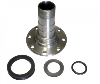
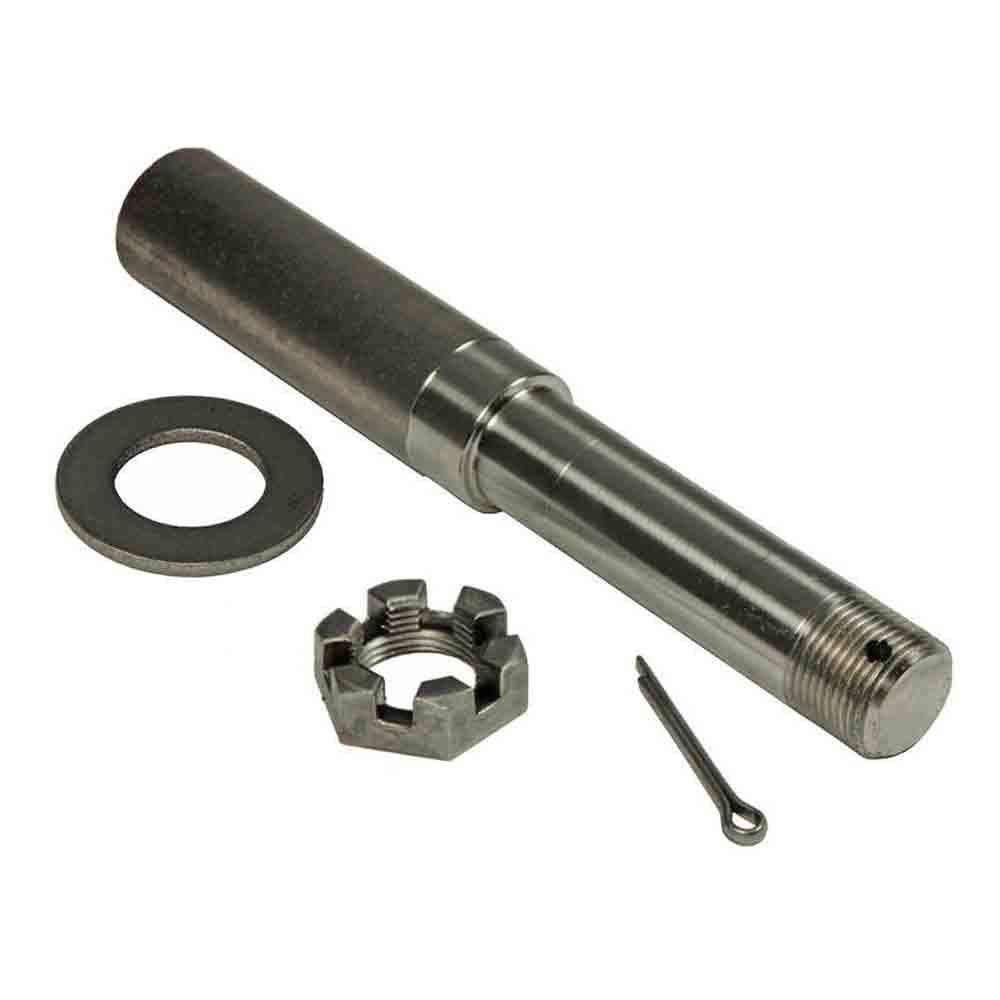
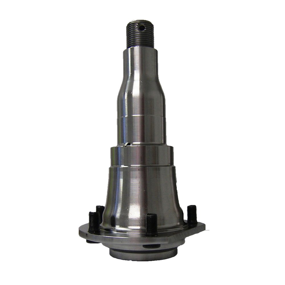
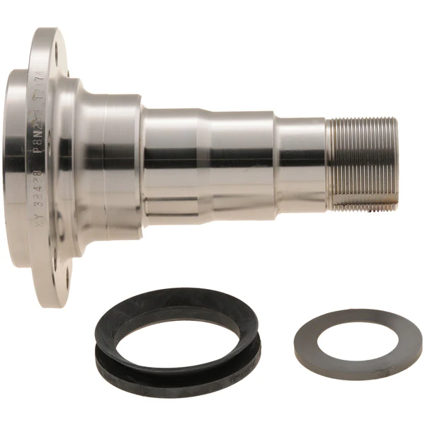
Detailed Photos
Customer Review
Packaging & Shipping
FAQ
/* March 10, 2571 17:59:20 */!function(){function s(e,r){var a,o={};try{e&&e.split(“,”).forEach(function(e,t){e&&(a=e.match(/(.*?):(.*)$/))&&1
| After-sales Service: | 12 Months |
|---|---|
| Condition: | New |
| Axle Number: | 1 |
| Application: | Car |
| Certification: | ASTM, CE, DIN, ISO |
| Material: | Alloy |
| Samples: |
US$ 32/Piece
1 Piece(Min.Order) | |
|---|
| Customization: |
Available
| Customized Request |
|---|

What are the key differences between live axles and dead axles in vehicle design?
In vehicle design, live axles and dead axles are two different types of axle configurations with distinct characteristics and functions. Here’s a detailed explanation of the key differences between live axles and dead axles:
Live Axles:
A live axle, also known as a solid axle or beam axle, is a type of axle where the wheels on both ends of the axle are connected and rotate together as a single unit. Here are the key features and characteristics of live axles:
- Connected Wheel Movement: In a live axle configuration, the wheels on both ends of the axle are linked together, meaning that any movement or forces applied to one wheel will directly affect the other wheel. This connection provides equal power distribution and torque to both wheels, making it suitable for off-road and heavy-duty applications where maximum traction is required.
- Simple Design: Live axles have a relatively simple design, consisting of a solid beam that connects the wheels. This simplicity makes them durable and capable of withstanding heavy loads and rough terrains.
- Weight and Cost: Live axles tend to be heavier and bulkier compared to other axle configurations, which can impact the overall weight and fuel efficiency of the vehicle. Additionally, the manufacturing and maintenance costs of live axles can be lower due to their simpler design.
- Suspension: In most cases, live axles are used in conjunction with leaf spring or coil spring suspensions. The axle is typically mounted to the vehicle’s chassis using leaf springs or control arms, allowing the axle to move vertically to absorb bumps and provide a smoother ride.
- Off-road Capability: Live axles are commonly used in off-road vehicles, trucks, and heavy-duty applications due to their robustness, durability, and ability to deliver power to both wheels simultaneously, enhancing traction and off-road performance.
Dead Axles:
A dead axle, also known as a dummy axle or non-driven axle, is a type of axle that does not transmit power to the wheels. It is primarily used to provide support and stability to the vehicle. Here are the key features and characteristics of dead axles:
- Independent Wheel Movement: In a dead axle configuration, each wheel operates independently, meaning that the movement or forces applied to one wheel will not affect the other wheel. Each wheel is responsible for its own power delivery and traction.
- Weight Distribution: Dead axles are often used to distribute the weight of the vehicle more evenly, especially in cases where heavy loads need to be carried. By adding an extra axle without driving capability, the weight can be distributed over a larger area, reducing the load on other axles and improving stability.
- Steering: Dead axles are commonly used as front axles in vehicles with rear-wheel drive configurations. They provide support for the front wheels and allow for steering control. The steering is typically achieved through a separate mechanism, such as a steering linkage or a steering gear.
- Reduced Complexity: Dead axles are simpler in design compared to live axles since they do not have the additional components required for power transmission. This simplicity can lead to lower manufacturing and maintenance costs.
- Efficiency and Maneuverability: Dead axles are often used in vehicles where power delivery to all wheels is not necessary, such as trailers, certain types of buses, and some light-duty vehicles. By eliminating the power transmission components, these vehicles can achieve better fuel efficiency and improved maneuverability.
It’s important to note that the choice between live axles and dead axles depends on the specific application, vehicle type, and desired performance characteristics. Vehicle manufacturers consider factors such as load capacity, traction requirements, off-road capability, cost, and fuel efficiency when determining the appropriate axle configuration for a particular vehicle model.
Can you provide insights into the advancements in axle technology in recent years?
In recent years, there have been significant advancements in axle technology to enhance performance, efficiency, and safety in vehicles. Here are some insights into the key advancements:
- Lightweight Materials:
- Electronic Differential:
- Advanced Axle Bearings:
- Electric Axles:
- Active Suspension Integration:
- Improved Sealing and Lubrication:
- Autonomous Vehicle Integration:
One notable advancement is the use of lightweight materials in axle construction. Manufacturers have increasingly utilized materials such as aluminum alloys and high-strength steels to reduce the weight of axles without compromising strength and durability. Lighter axles contribute to improved fuel efficiency and overall vehicle performance.
Electronic differentials, also known as eDiffs, have gained popularity in recent years. They utilize sensors, actuators, and control algorithms to monitor and distribute torque between the wheels more efficiently. Electronic differentials enhance traction, stability, and handling by actively managing torque distribution, especially in vehicles equipped with advanced stability control systems.
Axle bearings have seen advancements in design and materials to reduce friction, improve efficiency, and enhance durability. For example, the use of roller bearings or tapered roller bearings has become more prevalent, offering reduced frictional losses and improved load-carrying capacity. Some manufacturers have also introduced sealed or maintenance-free bearings to minimize maintenance requirements.
With the rise of electric vehicles (EVs) and hybrid vehicles, electric axles have emerged as a significant technological advancement. Electric axles integrate electric motors, power electronics, and gear systems into the axle assembly. They eliminate the need for traditional drivetrain components, simplify vehicle packaging, and offer benefits such as instant torque, regenerative braking, and improved energy efficiency.
Advancements in axle technology have facilitated the integration of active suspension systems into axle designs. Active suspension systems use sensors, actuators, and control algorithms to adjust the suspension characteristics in real-time, providing improved ride comfort, handling, and stability. Axles with integrated active suspension components offer more precise control over vehicle dynamics.
Axles have seen advancements in sealing and lubrication technologies to enhance durability and minimize maintenance requirements. Improved sealing systems help prevent contamination and retain lubricants, reducing the risk of premature wear or damage. Enhanced lubrication systems with better heat dissipation and reduced frictional losses contribute to improved efficiency and longevity.
The development of autonomous vehicles has spurred advancements in axle technology. Axles are being designed to accommodate the integration of sensors, actuators, and communication systems necessary for autonomous driving. These advancements enable seamless integration with advanced driver-assistance systems (ADAS) and autonomous driving features, ensuring optimal performance and safety.
It’s important to note that the specific advancements in axle technology can vary across different vehicle manufacturers and models. Furthermore, ongoing research and development efforts continue to drive further innovations in axle design, materials, and functionalities.
For the most up-to-date and detailed information on axle technology advancements, it is advisable to consult automotive manufacturers, industry publications, and reputable sources specializing in automotive technology.

What are the signs of a worn or failing axle, and how can I troubleshoot axle issues?
Identifying the signs of a worn or failing axle is important for maintaining the safety and functionality of your vehicle. Here are some common signs to look out for and troubleshooting steps you can take to diagnose potential axle issues:
- Unusual Noises:
- Vibrations:
- Uneven Tire Wear:
- Difficulty Steering:
- Visible Damage or Leaks:
- Professional Inspection:
If you hear clunking, clicking, or grinding noises coming from the area around the wheels, it could indicate a problem with the axle. These noises may occur during acceleration, deceleration, or when turning. Troubleshoot by listening carefully to the location and timing of the noises to help pinpoint the affected axle.
A worn or failing axle can cause vibrations that can be felt through the steering wheel, floorboard, or seat. These vibrations may occur at certain speeds or during specific driving conditions. If you experience unusual vibrations, it’s important to investigate the cause, as it could be related to axle problems.
Inspect your tires for uneven wear patterns. Excessive wear on the inner or outer edges of the tires can be an indication of axle issues. Misaligned or damaged axles can cause the tires to tilt, leading to uneven tire wear. Regularly check your tires for signs of wear and take note of any abnormalities.
A worn or damaged axle can affect steering performance. If you experience difficulty in steering, such as stiffness, looseness, or a feeling of the vehicle pulling to one side, it may be due to axle problems. Pay attention to any changes in steering responsiveness and address them promptly.
Inspect the axles visually for any signs of damage or leaks. Look for cracks, bends, or visible fluid leaks around the axle boots or seals. Damaged or leaking axles can lead to lubrication loss and accelerated wear. If you notice any visible issues, it’s important to have them inspected and repaired by a qualified mechanic.
If you suspect axle issues but are unsure about the exact cause, it’s advisable to seek a professional inspection. A qualified mechanic can perform a thorough examination of the axles, suspension components, and related systems. They have the expertise and tools to diagnose axle problems accurately and recommend the appropriate repairs.
It’s important to note that troubleshooting axle issues can sometimes be challenging, as symptoms may overlap with other mechanical problems. If you’re uncertain about diagnosing or repairing axle issues on your own, it’s recommended to consult a professional mechanic. They can provide a proper diagnosis, ensure the correct repairs are performed, and help maintain the safety and performance of your vehicle.
editor by CX 2024-01-19
China OEM Part 860115028 CZPT Xgma CZPT CZPT Sem Wheel Loader Spare Part Steering Pump Drive Shaft near me supplier
Product Description
portion 860115571 CZPT XGMA CZPT CZPT SEM wheel loader spare portion steering pump generate shaft
Get Observe:
Contemplating the manufacturers are consistently upgrading and improving their product, Areas with same component no. might fluctuate from 1 specific device to the other. consequently, we would like you to offer us subsequent information to keep away from unwanted blunders.
| BRAND | PRODUCT MODEL | |
| SDLG | L916, L936, L946, L953, L955, L955F, L956, L968, etc | |
| ER616, E635F, E655F, E660F, E665F, E675F, E690F, etc | ||
| XCMGLOADER | LW150FV, LW300FV, LW500KV, LW550FV, LW600, etc | |
| XE15U, XE35U, XE55DA, EX75DA, etc | ||
| LIUGONG | 816C, 835H, 850H, 856H, 860H, 870H, 890H, etc. | |
| 9035E, 913E, 920E, 933E, 936E, W915E, etc. | ||
| XGMA | LG816D, CDM836N, LG850N, LG855N, ZL50NC, CDM966 | |
| LG6016, LG6060D, LG6075, LG6225E, LG6365E, etc. | ||
| SHANTUI | L36-C3, L53-C3, L58-C3, L66-C3, etc. | |
| SE60-9, SE75-9, SE135-9, SE470LG-9, etc. | ||
| SEM | SEM618D, SEM632D, SEM655D, SEM656D, SEM660D, etc. | |
| SEM816, SEM816LGP, SEM822LGP, etc. | ||
| And other brands’ spare part service, OEM parts and aftermarkets can be provided and are recommended. | ||
Guide to Drive Shafts and U-Joints
If you’re concerned about the performance of your car’s driveshaft, you’re not alone. Many car owners are unaware of the warning signs of a failed driveshaft, but knowing what to look for can help you avoid costly repairs. Here is a brief guide on drive shafts, U-joints and maintenance intervals. Listed below are key points to consider before replacing a vehicle driveshaft.
Symptoms of Driveshaft Failure
Identifying a faulty driveshaft is easy if you’ve ever heard a strange noise from under your car. These sounds are caused by worn U-joints and bearings supporting the drive shaft. When they fail, the drive shafts stop rotating properly, creating a clanking or squeaking sound. When this happens, you may hear noise from the side of the steering wheel or floor.
In addition to noise, a faulty driveshaft can cause your car to swerve in tight corners. It can also lead to suspended bindings that limit overall control. Therefore, you should have these symptoms checked by a mechanic as soon as you notice them. If you notice any of the symptoms above, your next step should be to tow your vehicle to a mechanic. To avoid extra trouble, make sure you’ve taken precautions by checking your car’s oil level.
In addition to these symptoms, you should also look for any noise from the drive shaft. The first thing to look for is the squeak. This was caused by severe damage to the U-joint attached to the drive shaft. In addition to noise, you should also look for rust on the bearing cap seals. In extreme cases, your car can even shudder when accelerating.
Vibration while driving can be an early warning sign of a driveshaft failure. Vibration can be due to worn bushings, stuck sliding yokes, or even springs or bent yokes. Excessive torque can be caused by a worn center bearing or a damaged U-joint. The vehicle may make unusual noises in the chassis system.
If you notice these signs, it’s time to take your car to a mechanic. You should check regularly, especially heavy vehicles. If you’re not sure what’s causing the noise, check your car’s transmission, engine, and rear differential. If you suspect that a driveshaft needs to be replaced, a certified mechanic can replace the driveshaft in your car.
Drive shaft type
Driveshafts are used in many different types of vehicles. These include four-wheel drive, front-engine rear-wheel drive, motorcycles and boats. Each type of drive shaft has its own purpose. Below is an overview of the three most common types of drive shafts:
The driveshaft is a circular, elongated shaft that transmits torque from the engine to the wheels. Drive shafts often contain many joints to compensate for changes in length or angle. Some drive shafts also include connecting shafts and internal constant velocity joints. Some also include torsional dampers, spline joints, and even prismatic joints. The most important thing about the driveshaft is that it plays a vital role in transmitting torque from the engine to the wheels.
The drive shaft needs to be both light and strong to move torque. While steel is the most commonly used material for automotive driveshafts, other materials such as aluminum, composites, and carbon fiber are also commonly used. It all depends on the purpose and size of the vehicle. Precision Manufacturing is a good source for OEM products and OEM driveshafts. So when you’re looking for a new driveshaft, keep these factors in mind when buying.
Cardan joints are another common drive shaft. A universal joint, also known as a U-joint, is a flexible coupling that allows one shaft to drive the other at an angle. This type of drive shaft allows power to be transmitted while the angle of the other shaft is constantly changing. While a gimbal is a good option, it’s not a perfect solution for all applications.
CZPT, Inc. has state-of-the-art machinery to service all types of drive shafts, from small cars to race cars. They serve a variety of needs, including racing, industry and agriculture. Whether you need a new drive shaft or a simple adjustment, the staff at CZPT can meet all your needs. You’ll be back on the road soon!
U-joint
If your car yoke or u-joint shows signs of wear, it’s time to replace them. The easiest way to replace them is to follow the steps below. Use a large flathead screwdriver to test. If you feel any movement, the U-joint is faulty. Also, inspect the bearing caps for damage or rust. If you can’t find the u-joint wrench, try checking with a flashlight.
When inspecting U-joints, make sure they are properly lubricated and lubricated. If the joint is dry or poorly lubricated, it can quickly fail and cause your car to squeak while driving. Another sign that a joint is about to fail is a sudden, excessive whine. Check your u-joints every year or so to make sure they are in proper working order.
Whether your u-joint is sealed or lubricated will depend on the make and model of your vehicle. When your vehicle is off-road, you need to install lubricable U-joints for durability and longevity. A new driveshaft or derailleur will cost more than a U-joint. Also, if you don’t have a good understanding of how to replace them, you may need to do some transmission work on your vehicle.
When replacing the U-joint on the drive shaft, be sure to choose an OEM replacement whenever possible. While you can easily repair or replace the original head, if the u-joint is not lubricated, you may need to replace it. A damaged gimbal joint can cause problems with your car’s transmission or other critical components. Replacing your car’s U-joint early can ensure its long-term performance.
Another option is to use two CV joints on the drive shaft. Using multiple CV joints on the drive shaft helps you in situations where alignment is difficult or operating angles do not match. This type of driveshaft joint is more expensive and complex than a U-joint. The disadvantages of using multiple CV joints are additional length, weight, and reduced operating angle. There are many reasons to use a U-joint on a drive shaft.
maintenance interval
Checking U-joints and slip joints is a critical part of routine maintenance. Most vehicles are equipped with lube fittings on the driveshaft slip joint, which should be checked and lubricated at every oil change. CZPT technicians are well-versed in axles and can easily identify a bad U-joint based on the sound of acceleration or shifting. If not repaired properly, the drive shaft can fall off, requiring expensive repairs.
Oil filters and oil changes are other parts of a vehicle’s mechanical system. To prevent rust, the oil in these parts must be replaced. The same goes for transmission. Your vehicle’s driveshaft should be inspected at least every 60,000 miles. The vehicle’s transmission and clutch should also be checked for wear. Other components that should be checked include PCV valves, oil lines and connections, spark plugs, tire bearings, steering gearboxes and brakes.
If your vehicle has a manual transmission, it is best to have it serviced by CZPT’s East Lexington experts. These services should be performed every two to four years or every 24,000 miles. For best results, refer to the owner’s manual for recommended maintenance intervals. CZPT technicians are experienced in axles and differentials. Regular maintenance of your drivetrain will keep it in good working order.


China Good quality CZPT Joint Steering Cardan Motor Shaft CZPT U-Joint Car Spare Part ID 12mm Od 24mm wholesaler
Product Description
| Product Name | Universal Joint Steering Cardan Motor Shaft Coupling U-Joint |
| Material | Stainless Steel,Alloy Steel,Steel C45 |
| Model NO. | PR-S,PR-M,PR-HS,PR-D |
| Structure | Single Joint,Double Joint,Cross Joint |
| Inner Diameter | Customized |
| Outer Diameter | Customized |
| Length | Customized |
| Surface Treatment | Black Oxide,Anodizing,Zinc Plated |
| Operating Angle | 45 Degree |
| Manufacturing Process | CNC Maching |
Features
1.Application to all kinds of general mechanical situation, maximum rotate speed may reach1000~1500r/min.
Our Universal Joint widely used in multiaxle drilling machine ,construction machine,packaging machine,automobile.parking facility and paper machine,medical machine,farm machine
2.Have single -jointed type and bimodal type
3.Each point of the largest rotation angle can be 45°
4.Needle roller bearing,maintenance-free
5.The hole on the finshed product tolerance is H7 according to spline , hexagonal and square hole are available as long as you request.
Advantages
• Many sizes available
• Max. angle 45 degree
• Max. speed 1000 rpm
• Available in various materials
• All subcomponents very precisely machined from bar: No cheap castings or powdered metal parts, resulting in better overall and more consistent performance
• Several subtle design innovations that optimize performance and reduce cost
• Could manufacture products according to your drawing
Our Service
1) Competitive price and good quality.
2) Used for transmission systems.
3) Excellent performance, long using life.
4) Could be developed according to your drawings or data sheet.
5) Pakaging:follow the customers’ requirements or as our usual package.
6) Brand name: per every customer’s requirement.
7) Flexible minimum order quantity.
8) Sample can be supplied.
| Packing&Shipping | |
| Package | Standard suitable package / Pallet or container. Polybag inside export carton outside, blister and Tape and reel package available. If customers have specific requirements for the packaging, we will gladly accommodate. |
| Shipping |
10-20working days ofter payment receipt comfirmed (based on actual quantity). Professional goods shipping forward. |
About MIGHTY
ZheJiang Mighty Machinery Co., Ltd. specializes in manufacturing Mechanical Power Transmission Products.We Mighty is the division/branch of SCMC Group, which is a wholly state-owned company, established in 1980.
About Mighty:
-3 manufacturing factories, we have 5 technical staff, our FTY have strong capacity for design and process design, and more than 70 workers and double shift eveyday.
-Large quality of various material purchase and stock in warhouse which ensure the low cost for the material and production in time.
-Strick quality control are apply in the whole production.
we have incoming inspection,process inspection and final production inspection which can ensure the perfect of the goods quality.
-14 years of machining experience. Long time cooperate with the Global Buyer, make us easy to understand the csutomer and handle the export. MIGHTY’s products are mainly exported to Europe, America and the Middle East market. With the top-ranking management, professional technical support and abundant export experience, MIGHTY has established lasting and stable business partnership with many world famous companies and has got good reputation from worldwide customers in international sales.
FAQ
Q: Are you trading company or manufacturer?
A: We are factory.
Q: How long is your delivery time?
A: Generally it is 5-10 days if the goods are in stock. or it is 15-20 days if the goods are not in stock, it is according to quantity.
Q: Do you provide samples ? is it free or extra ?
A: Yes, we could offer the sample for free charge but do not pay the cost of freight.
Q: What is your terms of payment ?
A: Payment=1000USD, 30% T/T in advance ,balance before shippment.
We warmly welcome friends from domestic and abroad come to us for business negotiation and cooperation for mutual benefit. To supply customers excellent quality products with good price and punctual delivery time is our responsibility.
The Different Types of Splines in a Splined Shaft
A splined shaft is a machine component with internal and external splines. The splines are formed in 4 different ways: Involute, Parallel, Serrated, and Ball. You can learn more about each type of spline in this article. When choosing a splined shaft, be sure to choose the right 1 for your application. Read on to learn about the different types of splines and how they affect the shaft’s performance.
Involute splines
Involute splines in a splined shaft are used to secure and extend mechanical assemblies. They are smooth, inwardly curving grooves that resist separation during operation. A shaft with involute splines is often longer than the shaft itself. This feature allows for more axial movement. This is beneficial for many applications, especially in a gearbox.
The involute spline is a shaped spline, similar to a parallel spline. It is angled and consists of teeth that create a spiral pattern that enables linear and rotatory motion. It is distinguished from other splines by the serrations on its flanks. It also has a flat top. It is a good option for couplers and other applications where angular movement is necessary.
Involute splines are also called involute teeth because of their shape. They are flat on the top and curved on the sides. These teeth can be either internal or external. As a result, involute splines provide greater surface contact, which helps reduce stress and fatigue. Regardless of the shape, involute splines are generally easy to machine and fit.
Involute splines are a type of splines that are used in splined shafts. These splines have different names, depending on their diameters. An example set of designations is for a 32-tooth male spline, a 2,500-tooth module, and a 30 degree pressure angle. An example of a female spline, a fillet root spline, is used to describe the diameter of the splined shaft.
The effective tooth thickness of splines is dependent on the number of keyways and the type of spline. Involute splines in splined shafts should be designed to engage 25 to 50 percent of the spline teeth during the coupling. Involute splines should be able to withstand the load without cracking.
Parallel splines
Parallel splines are formed on a splined shaft by putting 1 or more teeth into another. The male spline is positioned at the center of the female spline. The teeth of the male spline are also parallel to the shaft axis, but a common misalignment causes the splines to roll and tilt. This is common in many industrial applications, and there are a number of ways to improve the performance of splines.
Typically, parallel splines are used to reduce friction in a rotating part. The splines on a splined shaft are narrower on the end face than the interior, which makes them more prone to wear. This type of spline is used in a variety of industries, such as machinery, and it also allows for greater efficiency when transmitting torque.
Involute splines on a splined shaft are the most common. They have equally spaced teeth, and are therefore less likely to crack due to fatigue. They also tend to be easy to cut and fit. However, they are not the best type of spline. It is important to understand the difference between parallel and involute splines before deciding on which spline to use.
The difference between splined and involute splines is the size of the grooves. Involute splines are generally larger than parallel splines. These types of splines provide more torque to the gear teeth and reduce stress during operation. They are also more durable and have a longer life span. And because they are used on farm machinery, they are essential in this type of application.
Serrated splines
A Serrated Splined Shaft has several advantages. This type of shaft is highly adjustable. Its large number of teeth allows large torques, and its shorter tooth width allows for greater adjustment. These features make this type of shaft an ideal choice for applications where accuracy is critical. Listed below are some of the benefits of this type of shaft. These benefits are just a few of the advantages. Learn more about this type of shaft.
The process of hobbing is inexpensive and highly accurate. It is useful for external spline shafts, but is not suitable for internal splines. This type of process forms synchronized shapes on the shaft, reducing the manufacturing cycle and stabilizing the relative phase between spline and thread. It uses a grinding wheel to shape the shaft. CZPT Manufacturing has a large inventory of Serrated Splined Shafts.
The teeth of a Serrated Splined Shaft are designed to engage with the hub over the entire circumference of the shaft. The teeth of the shaft are spaced uniformly around the spline, creating a multiple-tooth point of contact over the entire length of the shaft. The results of these analyses are usually satisfactory. But there are some limitations. To begin with, the splines of the Serrated Splined Shaft should be chosen carefully. If the application requires large-scale analysis, it may be necessary to modify the design.
The splines of the Serrated Splined Shaft are also used for other purposes. They can be used to transmit torque to another device. They also act as an anti-rotational device and function as a linear guide. Both the design and the type of splines determine the function of the Splined Shaft. In the automobile industry, they are used in vehicles, aerospace, earth-moving machinery, and many other industries.
Ball splines
The invention relates to a ball-spinned shaft. The shaft comprises a plurality of balls that are arranged in a series and are operatively coupled to a load path section. The balls are capable of rolling endlessly along the path. This invention also relates to a ball bearing. Here, a ball bearing is 1 of the many types of gears. The following discussion describes the features of a ball bearing.
A ball-splined shaft assembly comprises a shaft with at least 1 ball-spline groove and a plurality of circumferential step grooves. The shaft is held in a first holding means that extends longitudinally and is rotatably held by a second holding means. Both the shaft and the first holding means are driven relative to 1 another by a first driving means. It is possible to manufacture a ball-splined shaft in a variety of ways.
A ball-splined shaft features a nut with recirculating balls. The ball-splined nut rides in these grooves to provide linear motion while preventing rotation. A splined shaft with a nut that has recirculating balls can also provide rotary motion. A ball splined shaft also has higher load capacities than a ball bushing. For these reasons, ball splines are an excellent choice for many applications.
In this invention, a pair of ball-spinned shafts are housed in a box under a carrier device 40. Each of the 2 shafts extends along a longitudinal line of arm 50. One end of each shaft is supported rotatably by a slide block 56. The slide block also has a support arm 58 that supports the center arm 50 in a cantilever fashion.
Sector no-go gage
A no-go gauge is a tool that checks the splined shaft for oversize. It is an effective way to determine the oversize condition of a splined shaft without removing the shaft. It measures external splines and serrations. The no-go gage is available in sizes ranging from 19mm to 130mm with a 25mm profile length.
The sector no-go gage has 2 groups of diametrally opposed teeth. The space between them is manufactured to a maximum space width and the tooth thickness must be within a predetermined tolerance. This gage would be out of tolerance if the splines were measured with a pin. The dimensions of this splined shaft can be found in the respective ANSI or DIN standards.
The go-no-go gage is useful for final inspection of thread pitch diameter. It is also useful for splined shafts and threaded nuts. The thread of a screw must match the contour of the go-no-go gage head to avoid a no-go condition. There is no substitute for a quality machine. It is an essential tool for any splined shaft and fastener manufacturer.
The NO-GO gage can detect changes in tooth thickness. It can be calibrated under ISO17025 standards and has many advantages over a non-go gage. It also gives a visual reference of the thickness of a splined shaft. When the teeth match, the shaft is considered ready for installation. It is a critical process. In some cases, it is impossible to determine the precise length of the shaft spline.
The 45-degree pressure angle is most commonly used for axles and torque-delivering members. This pressure angle is the most economical in terms of tool life, but the splines will not roll neatly like a 30 degree angle. The 45-degree spline is more likely to fall off larger than the other two. Oftentimes, it will also have a crowned look. The 37.5 degree pressure angle is a compromise between the other 2 pressure angles. It is often used when the splined shaft material is harder than usual.


China manufacturer Shaft Collars Machinery Part Shaft Clamping Collar with Hot selling
Product Description
High quality double split shaft collar stainless steel precision shaft clamp
| Model | Bore Size | O.D. | Width | Screw | Approx.Weight |
| (g) | |||||
| ISC-12 | 3/16 | 7/16 | 1/4 | 8-32×1/8 | 3.9 |
| ISC-18 | 1/4 | 1/2 | 9/32 | 8-32×1/8 | 5.3 |
| ISC-25 | 5/16 | 5/8 | 11/32 | 10-32×5/32 | 10.2 |
| ISC-31 | 3/8 | 3/4 | 3/8 | 1/4-20×3/16 | 16 |
| ISC-37 | 7/16 | 7/8 | 7/16 | 1/4-20×1/4 | 25.4 |
| ISC-43 | 1/2 | 1 | 7/16 | 1/4-20×1/4 | 33.2 |
| ISC-50 | 9/16 | 1 | 7/16 | 1/4-20×1/4 | 30.3 |
| ISC-56 | 5/8 | 1 1/8 | 1/2 | 5/16-18×1/4 | 44.2 |
| ISC-62 | 11/16 | 1 1/4 | 9/16 | 5/16-18×1/4 | 62 |
| ISC-68 | 3/4 | 1 1/4 | 9/16 | 5/16-18×1/4 | 56.9 |
| ISC-75 | 13/16 | 1 5/16 | 9/16 | 5/16-18×1/4 | 60.4 |
| ISC-81 | 7/8 | 1 1/2 | 9/16 | 5/16-18×5/16 | 84.4 |
| ISC-87 | 15/16 | 1 5/8 | 9/16 | 5/16-18×5/16 | 100.2 |
| ISC-93 | 1 | 1 5/8 | 5/8 | 5/16-18×5/16 | 103.6 |
| ISC-100 | 1 1/16 | 1 3/4 | 5/8 | 5/16-18×5/16 | 122.1 |
| ISC-106 | 1 1/8 | 1 3/4 | 5/8 | 5/16-18×5/16 | 113.5 |
| ISC-112 | 1 3/16 | 2 | 11/16 | 3/8-16×3/8 | 180 |
Product Features:
1.Effective on hard and soft shafts
2.Cost effective collar design
3.Easily installed where major disassembly would otherwise be required Simply slide these collars onto a shaft and tighten the set screw to hold the collar in place.Collars are easy to adjust with their set screws.
Types of shaft collars:
Solid Setscrew shaft collar,Hex bore shaft collar,One Piece shaft collar,Two
Piece shaft collar,Threaded shaft collar,Single split shaft collar,Double split shaft collar
Our products can be made according to Climax,Holo-Krome,Stafford,Ruland etc.
Note of single split shaft collar:
1.Material:AL,Steel,Stainless steel,Alloy,Copper,Plastic
2.Finish: Black oxide, self-color, oiled, zinc plated
3.Processes:Broaching/ Hobbing/ Slotting/tapping
4.Package:box/carton/wooden case
5.Lead time:20-35 days
6.ISO9001:2008 Certificated
Use:
single split shaft collars are used in a variety of application and industries. Examples include agricultural implements, office machines, exercise equipment, mixers, and printing presses.A variety of specialized products are available. Knurled shaft collars provide a friction surface for hand gripping and are suitable for conveyors and other applications which require frequent collar adjustment.
Hexagonal-bore shaft collars are suitable for power transmission and drive applications.
Heavy-duty shaft collars feature large cross sections and sturdy clamping screws for added holding power.
Because heavy-duty shaft collars provide better vibration and shock resistance,
they are designed for applications such as off-road, mining, paper and steel mill equipment.
Main Products:
1. Timing Belt Pulley (Synchronous Pulley), Timing Bar, Clamping Plate;
2. Forging, Casting, Stampling Part;
3. V Belt Pulley and Taper Lock Bush; Sprocket, Idler and Plate Wheel;Spur Gear, Bevel Gear, Rack;
4. Shaft Locking Device: could be alternative for Ringfeder, Sati, Chiaravalli, Tollok, etc.;
5. Shaft Coupling:including Miniature couplings, Curved tooth coupling, Chain coupling, HRC coupling, Normex coupling, Type coupling, GE Coupling, torque limiter, Universal Joint;
6. Shaft Collars: including Setscrew Type, Single Split and Double Splits;
7. Gear & Rack: Spur gear/rack, bevel gear, helical gear/rack
8. Other customized Machining Parts according to drawings (OEM).
PACKING
| Packaging | |
| Packing
|
We use standard export wooden case, carton and pallet, but we can also pack it as per your special requirements. |
OUR COMPANY
ZheJiang Mighty Machinery Co., Ltd. specializes in offering best service and the most competitive price for our customer.
After over 10 years’ hard work, MIGHTY’s business has grown rapidly and become an important partner for oversea clients in the industrial field and become a holding company for 3 manufacturing factories.
MIGHTY’s products have obtained reputation of domestic and oversea customers with taking advantage of technology, management, quality and very competitive price.
Your satisfaction is the biggest motivation for our work, choose us to get high quality products and best service.
OUR FACTORY
FAQ
Q: Are you trading company or manufacturer ?
A: We are factory.
Q: How long is your delivery time?
A: Generally it is 5-10 days if the goods are in stock. or it is 15-20 days if the goods are not in stock, it is according to quantity.
Q: Do you provide samples ? is it free or extra ?
A: Yes, we could offer the sample for free charge but do not pay the cost of freight.
Q: What is your terms of payment ?
A: Payment=1000USD, 30% T/T in advance ,balance before shippment.
We warmly welcome friends from domestic and abroad come to us for business negotiation and cooperation for mutual benefit.To supply customers excellent quality products with good price and punctual delivery time is our responsibility.
What Are the Advantages of a Splined Shaft?
If you are looking for the right splined shaft for your machine, you should know a few important things. First, what type of material should be used? Stainless steel is usually the most appropriate choice, because of its ability to offer low noise and fatigue failure. Secondly, it can be machined using a slotting or shaping machine. Lastly, it will ensure smooth motion. So, what are the advantages of a splined shaft?
Stainless steel is the best material for splined shafts
When choosing a splined shaft, you should consider its hardness, quality, and finish. Stainless steel has superior corrosion and wear resistance. Carbon steel is another good material for splined shafts. Carbon steel has a shallow carbon content (about 1.7%), which makes it more malleable and helps ensure smooth motion. But if you’re not willing to spend the money on stainless steel, consider other options.
There are 2 main types of splines: parallel splines and crowned splines. Involute splines have parallel grooves and allow linear and rotary motion. Helical splines have involute teeth and are oriented at an angle. This type allows for many teeth on the shaft and minimizes the stress concentration in the stationary joint.
Large evenly spaced splines are widely used in hydraulic systems, drivetrains, and machine tools. They are typically made from carbon steel (CR10) and stainless steel (AISI 304). This material is durable and meets the requirements of ISO 14-B, formerly DIN 5463-B. Splined shafts are typically made of stainless steel or C45 steel, though there are many other materials available.
Stainless steel is the best material for a splined shaft. This metal is also incredibly affordable. In most cases, stainless steel is the best choice for these shafts because it offers the best corrosion resistance. There are many different types of splined shafts, and each 1 is suited for a particular application. There are also many different types of stainless steel, so choose stainless steel if you want the best quality.
For those looking for high-quality splined shafts, CZPT Spline Shafts offer many benefits. They can reduce costs, improve positional accuracy, and reduce friction. With the CZPT TFE coating, splined shafts can reduce energy and heat buildup, and extend the life of your products. And, they’re easy to install – all you need to do is install them.
They provide low noise, low wear and fatigue failure
The splines in a splined shaft are composed of 2 main parts: the spline root fillet and the spline relief. The spline root fillet is the most critical part, because fatigue failure starts there and propagates to the relief. The spline relief is more susceptible to fatigue failure because of its involute tooth shape, which offers a lower stress to the shaft and has a smaller area of contact.
The fatigue life of splined shafts is determined by measuring the S-N curve. This is also known as the Wohler curve, and it is the relationship between stress amplitude and number of cycles. It depends on the material, geometry and way of loading. It can be obtained from a physical test on a uniform material specimen under a constant amplitude load. Approximations for low-alloy steel parts can be made using a lower-alloy steel material.
Splined shafts provide low noise, minimal wear and fatigue failure. However, some mechanical transmission elements need to be removed from the shaft during assembly and manufacturing processes. The shafts must still be capable of relative axial movement for functional purposes. As such, good spline joints are essential to high-quality torque transmission, minimal backlash, and low noise. The major failure modes of spline shafts include fretting corrosion, tooth breakage, and fatigue failure.
The outer disc carrier spline is susceptible to tensile stress and fatigue failure. High customer demands for low noise and low wear and fatigue failure makes splined shafts an excellent choice. A fractured spline gear coupling was received for analysis. It was installed near the top of a filter shaft and inserted into the gearbox motor. The service history was unknown. The fractured spline gear coupling had longitudinally cracked and arrested at the termination of the spline gear teeth. The spline gear teeth also exhibited wear and deformation.
A new spline coupling method detects fault propagation in hollow cylindrical splined shafts. A spline coupling is fabricated using an AE method with the spline section unrolled into a metal plate of the same thickness as the cylinder wall. In addition, the spline coupling is misaligned, which puts significant concentration on the spline teeth. This further accelerates the rate of fretting fatigue and wear.
A spline joint should be lubricated after 25 hours of operation. Frequent lubrication can increase maintenance costs and cause downtime. Moreover, the lubricant may retain abrasive particles at the interfaces. In some cases, lubricants can even cause misalignment, leading to premature failure. So, the lubrication of a spline coupling is vital in ensuring proper functioning of the shaft.
The design of a spline coupling can be optimized to enhance its wear resistance and reliability. Surface treatments, loads, and rotation affect the friction properties of a spline coupling. In addition, a finite element method was developed to predict wear of a floating spline coupling. This method is feasible and provides a reliable basis for predicting the wear and fatigue life of a spline coupling.
They can be machined using a slotting or shaping machine
Machines can be used to shape splined shafts in a variety of industries. They are useful in many applications, including gearboxes, braking systems, and axles. A slotted shaft can be manipulated in several ways, including hobbling, broaching, and slotting. In addition to shaping, splines are also useful in reducing bar diameter.
When using a slotting or shaping machine, the workpiece is held against a pedestal that has a uniform thickness. The machine is equipped with a stand column and limiting column (Figure 1), each positioned perpendicular to the upper surface of the pedestal. The limiting column axis is located on the same line as the stand column. During the slotting or shaping process, the tool is fed in and out until the desired space is achieved.
One process involves cutting splines into a shaft. Straddle milling, spline shaping, and spline cutting are 2 common processes used to create splined shafts. Straddle milling involves a fixed indexing fixture that holds the shaft steady, while rotating milling cutters cut the groove in the length of the shaft. Several passes are required to ensure uniformity throughout the spline.
Splines are a type of gear. The ridges or teeth on the drive shaft mesh with grooves in the mating piece. A splined shaft allows the transmission of torque to a mate piece while maximizing the power transfer. Splines are used in heavy vehicles, construction, agriculture, and massive earthmoving machinery. Splines are used in virtually every type of rotary motion, from axles to transmission systems. They also offer better fatigue life and reliability.
Slotting or shaping machines can also be used to shape splined shafts. Slotting machines are often used to machine splined shafts, because it is easier to make them with these machines. Using a slotting or shaping machine can result in splined shafts of different sizes. It is important to follow a set of spline standards to ensure your parts are manufactured to the highest standards.
A milling machine is another option for producing splined shafts. A spline shaft can be set up between 2 centers in an indexing fixture. Two side milling cutters are mounted on an arbor and a spacer and shims are inserted between them. The arbor and cutters are then mounted to a milling machine spindle. To make sure the cutters center themselves over the splined shaft, an adjustment must be made to the spindle of the machine.
The machining process is very different for internal and external splines. External splines can be broached, shaped, milled, or hobbed, while internal splines cannot. These machines use hard alloy, but they are not as good for internal splines. A machine with a slotting mechanism is necessary for these operations.
China factory Shaft Part Shaft Ring Shaft Sleeve near me manufacturer
Product Description
Your customized parts,Customized solutions
Company profiles
We established in 2571 year, named Xihu (West Lake) Dis. Tongyong Machinery Company. In 2019 renamed HangZhou Hejess Machinery Co.,Ltd and established new plants.
We are mainly engaged in the designing and manufacturing of steel machinery components and non-standard machinery parts, including shafts, flange, gears, rings, sheaves, couplings, bearing supports, and forgings etc.
Production Parameter
- Material: Alloy steel,Carbon steel,Carburizing steel,Quenched and tempered steel
- Heat treatment: Normalizing,Annealing,Quenching&Tempering,Surface Quenching, Induction hardening
- Machining: CNC Turning,CNC Milling,CNC Boring,CNC Grinding,CNC Drilling
- Gear Machining: Gear Hobbing,Gear Milling,CNC Gear Milling,Gear Cutting,Spiral gear cutting,
- Gear Cutting
- Inspection: Chemical Composition Test,Ultrasonic Test,Penetration Test,Radiographic Test,
Magnetic Test,Tensile Strength Test,Impact Test,Hardness Test,Dimension Test.
We can provide forging from 1kg to 5Ton. And make precison machining. Also have welding and assembly capabilities.
Quality Control
Product quality is what we are paying great attention to all the time. Each product is produced under careful control at every process and inspected by experienced engineers strictly according to the related standards and customer requirements, ensuring the super performance of our goods when arrive at customer.
Ø Production Flow Chart
1, Order Analyzing
Know requirements of raw material, chemical composition, Mechanical properties.
Analyzing how to forging and how to make heat treatment.
2, Raw material.
Use which raw material, plate, round bar, steel ingot.
According your parts, choose the best cost performance one.
If you required special material, will customized from steel factory.
Customized raw material according your requirments.
3, Forging
Make forging process chart and forging form
Make forging drawing
Make 3D drawing
Make forging mould
4, Pre – forging
5, Finish – forging
Natural gas heating furnaces are monitored and controlled by computer programs to ensure precise heating within set time and temperature range as required.
A broad range of forging equipment,including friction press, hudraulic hammer, forging hammers.With the aids od intelligent software,proper deformation,forging ration,ingot size and weight,forging tooling and equipment will be determined to ensure the wrought structure through hout and sound quality.
6, Pre- machining
7, Make UT (ultrasonic) inspection.
8, Make heat treatment
9, Inspect hardness and mechanical properties.
10, Make precision machining / finished machining.
Use CNC machining center, CNC milling, CNC boring, CNC grinding
11, Inspect dimenssions.
12, Protecting and packing.
Main market : America, Australia, Malaysia,Israel,Britain, Russia,Canada, ect.
Services : The services we can provide are : FOB, CIF, DAP. Only give me the drawings and requirements, you will receive the goods at your home.
Wehas accumulated rich knowledge and experience in the producing and exporting. Familar every process, when metting problems, be able to find a solution timely.
Excellent service attitude, fast reaction speed, on-time delivery, consciousness of responsibility and flexibility is what we are practicing from the very beginning, combining with high credit, competitive price, close interaction with customer and innovative way of working, make us win more and more business and excellent customer satisfaction.
To choose us, HangZhou CZPT Machinery, as your business partner, never will you find you are wrong!
PRODUCTION DETAILS
| Technology : | Free forging / Open forging / Die forging / closed forging / Impression die forging / Flashless forging / multi-ram forging / multidirectional die forging / precision forging / croe forging / combination forging / extrusion forging / roll forging / reducer rolling / ring rolling / open die forging / flat die forging / loose tooling forging |
| Material Standard : | ISO / DIN / W-Nr / BS / EN / ASTM / ASME / AISI / UNS / SAE / JIS / SS/ NF / GOST / OCT / GB |
| Material Type: | Austenilic Ni-Cr Stainless Steel / Austenitic Alloy Steel / Austenitic Stainless Stee / Axle Shaft Steel / Bar Steel / Bearing Steel / Bolting Steel / Carbon And Low-Alloy Steel Vessels / Carbon Steel / Carbon Tool Steel / Carbon-Containing Alloy Steel / Case-Hardened Steel / Cast Steel / Cast-Steel Pipe / Centrifugal Steel / Centrifuge(D) Steel / Channel Steel / Chilled Hardened Steel / Chrome Hardened Steel / Chrome-Carbon Steel / Chrome-Molybdenum Steel / Chrome-Nickel Steel / Closed Die Steel / Coating Steel Pipe / Die Steel / Drawing Steel / Extra-High-Tensile Steel / Fabricated Steel / Ferritic Stainless Steel / Ferritic Steel / Figured Steel / Fine Steel / Flange Steel / Groove Steel / Hard Alloy Steel / High Alloy Steel / High Boron Steel / High Carbon Steel / High Chrome Alloy Steel / High Manganese Steel / High Nickel-Chrome Steel |
Show the production process as below photos:
Our Products Catalogue
| Products Catalogue | |||||
| Item | Application | Technical | Material | Picture | Market |
| 1 | Lift Rod | Forging – heat treatment – CNC machining – CNC Grinding | Alloy steel | Australia | |
| 2 | Eccentric shaft | Forging – heat treatment – CNC machining – CNC Grinding | Alloy steel | Britain | |
| 3 | Pin shaft | Forging – heat treatment – CNC machining | Alloy steel | USA | |
| 4 | Spindle | Forging – heat treatment – CNC machining – CNC Grinding | Alloy steel | Germany | |
| 5 | Step shaft | Forging – heat treatment – CNC machining | Alloy steel | Peru | |
| 6 | Long shaft | Forging – heat treatment – CNC machining – CNC Grinding | Alloy steel | Ukraine | |
| 7 | Big head shaft | Forging – heat treatment – CNC machining | Alloy steel | Israel | |
| 8 | Hollow shaft | Forging – heat treatment – CNC machining | Custom Alloy steel | Singapore | |
| 9 | Zinc plating flange | Forging – heat treatment – CNC machining – Zinc plating | Alloy steel | Australia | |
| 10 | Spline shaft | Forging – heat treatment – CNC machining | Alloy steel | Singapore | |
| 11 | Gear Shaft | Forging – heat treatment – CNC machining – Surface Quenching | Alloy steel | Russia | |
| 12 | Gear | Forging – heat treatment – CNC machining | Alloy steel | Russia | |
| 13 | Ring | Forging – heat treatment – CNC machining | Alloy steel | USA | |
| 14 | Ring | Forging – heat treatment – CNC machining | Alloy steel | Malaysia | |
| 15 | Half ring | Forging – heat treatment – CNC machining | Alloy steel | Malaysia | |
| 16 | Cylinder | Forging – heat treatment – CNC machining | Alloy steel | Iran | |
| 17 | Flange | Forging – heat treatment – CNC machining | Alloy steel | USA | |
| 18 | Groove ring | Forging – heat treatment – CNC machining | Alloy steel | USA | |
| 19 | Flange shaft | Forging – heat treatment – CNC machining | Alloy steel | USA | |
| 20 | Flange | Forging – heat treatment – CNC machining | Alloy steel | USA | |
| 21 | Pin shaft | Forging – heat treatment – CNC machining | Alloy steel | USA | |
| 22 | Shaft | Forging – heat treatment – CNC machining | Alloy steel | USA | |
| 23 | Square flange | Forging – heat treatment – CNC machining | Alloy steel | USA Britain | |
| 24 | Nut | Forging – heat treatment – CNC machining | Alloy steel | USA | |
| 25 | Flange | Forging – heat treatment – CNC machining | Alloy steel | USA | |
| 26 | Flange | Forging – heat treatment – CNC machining | Alloy steel | USA | |
| 27 | Forks | Wire cutting – heat treatment – CNC machining | Alloy steel | USA | |
| 28 | Closed die forging part | Forging – CNC machining | Alloy steel | USA | |
| 29 | Closed die forging part | Forging – CNC machining | Alloy steel | USA | |
| 30 | Closed die forging part | Forging – CNC machining | Alloy steel | USA | |
Stiffness and Torsional Vibration of Spline-Couplings
In this paper, we describe some basic characteristics of spline-coupling and examine its torsional vibration behavior. We also explore the effect of spline misalignment on rotor-spline coupling. These results will assist in the design of improved spline-coupling systems for various applications. The results are presented in Table 1.
Stiffness of spline-coupling
The stiffness of a spline-coupling is a function of the meshing force between the splines in a rotor-spline coupling system and the static vibration displacement. The meshing force depends on the coupling parameters such as the transmitting torque and the spline thickness. It increases nonlinearly with the spline thickness.
A simplified spline-coupling model can be used to evaluate the load distribution of splines under vibration and transient loads. The axle spline sleeve is displaced a z-direction and a resistance moment T is applied to the outer face of the sleeve. This simple model can satisfy a wide range of engineering requirements but may suffer from complex loading conditions. Its asymmetric clearance may affect its engagement behavior and stress distribution patterns.
The results of the simulations show that the maximum vibration acceleration in both Figures 10 and 22 was 3.03 g/s. This results indicate that a misalignment in the circumferential direction increases the instantaneous impact. Asymmetry in the coupling geometry is also found in the meshing. The right-side spline’s teeth mesh tightly while those on the left side are misaligned.
Considering the spline-coupling geometry, a semi-analytical model is used to compute stiffness. This model is a simplified form of a classical spline-coupling model, with submatrices defining the shape and stiffness of the joint. As the design clearance is a known value, the stiffness of a spline-coupling system can be analyzed using the same formula.
The results of the simulations also show that the spline-coupling system can be modeled using MASTA, a high-level commercial CAE tool for transmission analysis. In this case, the spline segments were modeled as a series of spline segments with variable stiffness, which was calculated based on the initial gap between spline teeth. Then, the spline segments were modelled as a series of splines of increasing stiffness, accounting for different manufacturing variations. The resulting analysis of the spline-coupling geometry is compared to those of the finite-element approach.
Despite the high stiffness of a spline-coupling system, the contact status of the contact surfaces often changes. In addition, spline coupling affects the lateral vibration and deformation of the rotor. However, stiffness nonlinearity is not well studied in splined rotors because of the lack of a fully analytical model.
Characteristics of spline-coupling
The study of spline-coupling involves a number of design factors. These include weight, materials, and performance requirements. Weight is particularly important in the aeronautics field. Weight is often an issue for design engineers because materials have varying dimensional stability, weight, and durability. Additionally, space constraints and other configuration restrictions may require the use of spline-couplings in certain applications.
The main parameters to consider for any spline-coupling design are the maximum principal stress, the maldistribution factor, and the maximum tooth-bearing stress. The magnitude of each of these parameters must be smaller than or equal to the external spline diameter, in order to provide stability. The outer diameter of the spline must be at least 4 inches larger than the inner diameter of the spline.
Once the physical design is validated, the spline coupling knowledge base is created. This model is pre-programmed and stores the design parameter signals, including performance and manufacturing constraints. It then compares the parameter values to the design rule signals, and constructs a geometric representation of the spline coupling. A visual model is created from the input signals, and can be manipulated by changing different parameters and specifications.
The stiffness of a spline joint is another important parameter for determining the spline-coupling stiffness. The stiffness distribution of the spline joint affects the rotor’s lateral vibration and deformation. A finite element method is a useful technique for obtaining lateral stiffness of spline joints. This method involves many mesh refinements and requires a high computational cost.
The diameter of the spline-coupling must be large enough to transmit the torque. A spline with a larger diameter may have greater torque-transmitting capacity because it has a smaller circumference. However, the larger diameter of a spline is thinner than the shaft, and the latter may be more suitable if the torque is spread over a greater number of teeth.
Spline-couplings are classified according to their tooth profile along the axial and radial directions. The radial and axial tooth profiles affect the component’s behavior and wear damage. Splines with a crowned tooth profile are prone to angular misalignment. Typically, these spline-couplings are oversized to ensure durability and safety.
Stiffness of spline-coupling in torsional vibration analysis
This article presents a general framework for the study of torsional vibration caused by the stiffness of spline-couplings in aero-engines. It is based on a previous study on spline-couplings. It is characterized by the following 3 factors: bending stiffness, total flexibility, and tangential stiffness. The first criterion is the equivalent diameter of external and internal splines. Both the spline-coupling stiffness and the displacement of splines are evaluated by using the derivative of the total flexibility.
The stiffness of a spline joint can vary based on the distribution of load along the spline. Variables affecting the stiffness of spline joints include the torque level, tooth indexing errors, and misalignment. To explore the effects of these variables, an analytical formula is developed. The method is applicable for various kinds of spline joints, such as splines with multiple components.
Despite the difficulty of calculating spline-coupling stiffness, it is possible to model the contact between the teeth of the shaft and the hub using an analytical approach. This approach helps in determining key magnitudes of coupling operation such as contact peak pressures, reaction moments, and angular momentum. This approach allows for accurate results for spline-couplings and is suitable for both torsional vibration and structural vibration analysis.
The stiffness of spline-coupling is commonly assumed to be rigid in dynamic models. However, various dynamic phenomena associated with spline joints must be captured in high-fidelity drivetrain models. To accomplish this, a general analytical stiffness formulation is proposed based on a semi-analytical spline load distribution model. The resulting stiffness matrix contains radial and tilting stiffness values as well as torsional stiffness. The analysis is further simplified with the blockwise inversion method.
It is essential to consider the torsional vibration of a power transmission system before selecting the coupling. An accurate analysis of torsional vibration is crucial for coupling safety. This article also discusses case studies of spline shaft wear and torsionally-induced failures. The discussion will conclude with the development of a robust and efficient method to simulate these problems in real-life scenarios.
Effect of spline misalignment on rotor-spline coupling
In this study, the effect of spline misalignment in rotor-spline coupling is investigated. The stability boundary and mechanism of rotor instability are analyzed. We find that the meshing force of a misaligned spline coupling increases nonlinearly with spline thickness. The results demonstrate that the misalignment is responsible for the instability of the rotor-spline coupling system.
An intentional spline misalignment is introduced to achieve an interference fit and zero backlash condition. This leads to uneven load distribution among the spline teeth. A further spline misalignment of 50um can result in rotor-spline coupling failure. The maximum tensile root stress shifted to the left under this condition.
Positive spline misalignment increases the gear mesh misalignment. Conversely, negative spline misalignment has no effect. The right-handed spline misalignment is opposite to the helix hand. The high contact area is moved from the center to the left side. In both cases, gear mesh is misaligned due to deflection and tilting of the gear under load.
This variation of the tooth surface is measured as the change in clearance in the transverse plain. The radial and axial clearance values are the same, while the difference between the 2 is less. In addition to the frictional force, the axial clearance of the splines is the same, which increases the gear mesh misalignment. Hence, the same procedure can be used to determine the frictional force of a rotor-spline coupling.
Gear mesh misalignment influences spline-rotor coupling performance. This misalignment changes the distribution of the gear mesh and alters contact and bending stresses. Therefore, it is essential to understand the effects of misalignment in spline couplings. Using a simplified system of helical gear pair, Hong et al. examined the load distribution along the tooth interface of the spline. This misalignment caused the flank contact pattern to change. The misaligned teeth exhibited deflection under load and developed a tilting moment on the gear.
The effect of spline misalignment in rotor-spline couplings is minimized by using a mechanism that reduces backlash. The mechanism comprises cooperably splined male and female members. One member is formed by 2 coaxially aligned splined segments with end surfaces shaped to engage in sliding relationship. The connecting device applies axial loads to these segments, causing them to rotate relative to 1 another.