Product Description
Product Information:
>>Implementing ltalian Fiat wheel tractor advanced technology;
>>Using middle-arranged type transmission shaft and swing type center swing pin;
>>Internal structure:middle reducer,differential and final planet reducer;good rigidity with whole front axle case;
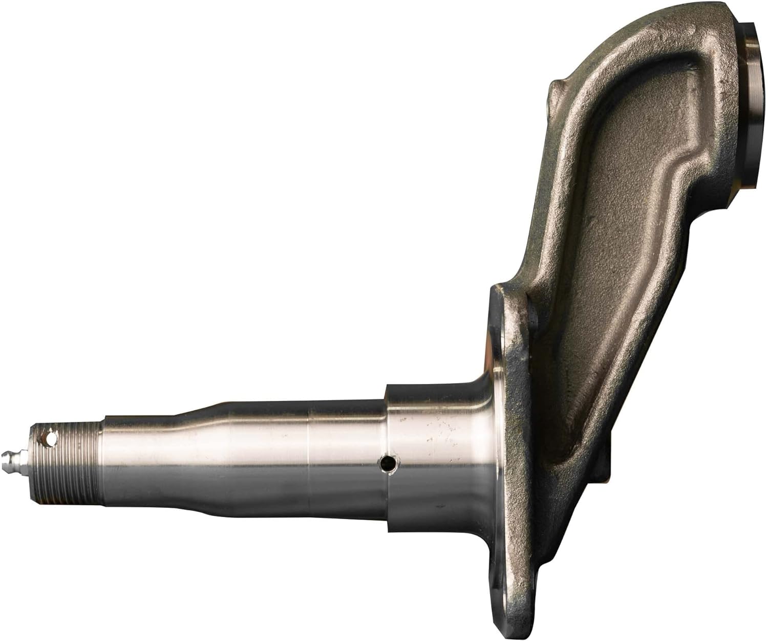
>>Roller bearing used on the end and knuckle bearing used for main pin for light and efficient steering;
>>Independent oil road,hydraulic pressure steering,steering angle to 50°;Single cylinder or double cylinder;
>>Adopting machining center and special machine for machining,planetary reduction gear for gear grinding,all the sealing parts are imported ones,not damaged assembly;
>>Adaptive for 135-180ps four-wheel driving tractor;
Technical Parameter:
| Performance parameter | RN1504 Front driving axle | |
| Driving ratio | 17.574 | |
| Outline dimension | 2150*506*380 | |
| Driving shaft front axle | ||
| Input shaft parameter | m=1.5875 z=21 α=30° | |
| Connection bolt between hub and spoke | 10*M20*1.5 | |
| Distance between spokes (mm) | 1900 | |
| The pressure of the hydraulic oil | 10±0.5 | |
| load bearing (kN) | 32.3 | |
| Net weight (KG) without oil | 365 | |
| Oil Volume | Middle (L) | |
| Round edge (L) | ||
| Front Axle Position |
Extroversion angle of front wheel | 1.5° |
| Introversion angle | 7° | |
| Retroverted angle | 6° | |
| Fore tie (mm) | 0~5 | |
| Steering method | fluid-link steering | |
| Swing angle of the front axle | 11° | |
| Maximum steering angle of front wheel | 50° | |
| Steering Cylinder |
Steering hydraulic cylinder type | Mid bidiractional |
| Diameter of steering hydraulic cylinder(mm) | 65 | |
| Steering hydraulic cylinder quantity | 1 | |
| Steering hydraulic cylinder travel(mm) | 270 | |
/* January 22, 2571 19:08:37 */!function(){function s(e,r){var a,o={};try{e&&e.split(“,”).forEach(function(e,t){e&&(a=e.match(/(.*?):(.*)$/))&&1
| Type: | Axle |
|---|---|
| Certification: | ISO9001 |
| Driving System Parts: | Front Axle |
| Transmission System Parts: | Drive Axle |
| Color: | Black |
| Model: | 1354 |
| Customization: |
Available
| Customized Request |
|---|

What are the safety considerations when working with axles, especially during repairs?
Working with axles, especially during repairs, requires careful attention to safety to prevent accidents and injuries. Here are some important safety considerations to keep in mind when working with axles:
1. Personal Protective Equipment (PPE):
Wear appropriate personal protective equipment, including safety goggles, gloves, and steel-toed boots. PPE helps protect against potential hazards such as flying debris, sharp edges, and accidental contact with heavy components.
2. Vehicle Stability:
Ensure that the vehicle is on a stable and level surface before working on the axles. Engage the parking brake and use wheel chocks to prevent unintended vehicle movement. The stability of the vehicle is crucial to maintain a safe working environment.
3. Lifting and Support:
Use proper lifting equipment, such as hydraulic jacks or vehicle lifts, to raise the vehicle safely. Follow the manufacturer’s guidelines for lifting points and weight capacities. Once the vehicle is lifted, support it securely with jack stands or other appropriate supports to prevent it from falling or shifting during repairs.
4. Lockout/Tagout:
If the repair work involves disconnecting or removing any electrical or mechanical components that could cause the axle or wheels to move, follow lockout/tagout procedures. This involves locking and tagging out the power source, so it cannot be accidentally energized while work is being performed.
5. Proper Tools and Equipment:
Use the correct tools and equipment for the job. Using improper tools or makeshift methods can lead to accidents and damage to the axle or surrounding components. Follow the manufacturer’s instructions and recommended procedures for disassembling, repairing, and reassembling the axle.
6. Proper Torque and Tightening:
When reassembling the axle components, use a torque wrench to ensure that fasteners are tightened to the manufacturer’s specifications. Over-tightening or under-tightening can lead to component failure or damage. Follow the recommended torque values provided by the vehicle manufacturer.
7. Safe Handling of Heavy Components:
Axle components can be heavy and cumbersome. Use appropriate lifting techniques and equipment, such as hoists or lifting straps, to safely handle heavy axle parts. Avoid lifting heavy components alone whenever possible and ask for assistance when needed.
8. Proper Disposal of Fluids and Waste:
If the repair involves draining fluids from the axle, such as differential oil, ensure proper disposal according to local regulations. Use appropriate containers to collect and store fluids and dispose of them at authorized collection points.
9. Training and Experience:
Working with axles requires knowledge and experience. If you are unfamiliar with axle repairs, consider seeking assistance from a qualified mechanic or technician who has the necessary training and expertise. If you decide to perform the repairs yourself, ensure that you have the appropriate knowledge and skills to carry out the task safely.
By following these safety considerations, you can help minimize the risk of accidents, injuries, and damage when working with axles, ensuring a safe working environment for yourself and others involved in the repair process.

Can you provide insights into the advancements in axle technology in recent years?
In recent years, there have been significant advancements in axle technology to enhance performance, efficiency, and safety in vehicles. Here are some insights into the key advancements:
- Lightweight Materials:
- Electronic Differential:
- Advanced Axle Bearings:
- Electric Axles:
- Active Suspension Integration:
- Improved Sealing and Lubrication:
- Autonomous Vehicle Integration:
One notable advancement is the use of lightweight materials in axle construction. Manufacturers have increasingly utilized materials such as aluminum alloys and high-strength steels to reduce the weight of axles without compromising strength and durability. Lighter axles contribute to improved fuel efficiency and overall vehicle performance.
Electronic differentials, also known as eDiffs, have gained popularity in recent years. They utilize sensors, actuators, and control algorithms to monitor and distribute torque between the wheels more efficiently. Electronic differentials enhance traction, stability, and handling by actively managing torque distribution, especially in vehicles equipped with advanced stability control systems.
Axle bearings have seen advancements in design and materials to reduce friction, improve efficiency, and enhance durability. For example, the use of roller bearings or tapered roller bearings has become more prevalent, offering reduced frictional losses and improved load-carrying capacity. Some manufacturers have also introduced sealed or maintenance-free bearings to minimize maintenance requirements.
With the rise of electric vehicles (EVs) and hybrid vehicles, electric axles have emerged as a significant technological advancement. Electric axles integrate electric motors, power electronics, and gear systems into the axle assembly. They eliminate the need for traditional drivetrain components, simplify vehicle packaging, and offer benefits such as instant torque, regenerative braking, and improved energy efficiency.
Advancements in axle technology have facilitated the integration of active suspension systems into axle designs. Active suspension systems use sensors, actuators, and control algorithms to adjust the suspension characteristics in real-time, providing improved ride comfort, handling, and stability. Axles with integrated active suspension components offer more precise control over vehicle dynamics.
Axles have seen advancements in sealing and lubrication technologies to enhance durability and minimize maintenance requirements. Improved sealing systems help prevent contamination and retain lubricants, reducing the risk of premature wear or damage. Enhanced lubrication systems with better heat dissipation and reduced frictional losses contribute to improved efficiency and longevity.
The development of autonomous vehicles has spurred advancements in axle technology. Axles are being designed to accommodate the integration of sensors, actuators, and communication systems necessary for autonomous driving. These advancements enable seamless integration with advanced driver-assistance systems (ADAS) and autonomous driving features, ensuring optimal performance and safety.
It’s important to note that the specific advancements in axle technology can vary across different vehicle manufacturers and models. Furthermore, ongoing research and development efforts continue to drive further innovations in axle design, materials, and functionalities.
For the most up-to-date and detailed information on axle technology advancements, it is advisable to consult automotive manufacturers, industry publications, and reputable sources specializing in automotive technology.

Can you explain the importance of axle alignment for vehicle stability and handling?
Axle alignment plays a crucial role in ensuring vehicle stability and handling characteristics. Proper alignment of the axles is essential for maintaining optimal tire contact with the road surface, minimizing tire wear, maximizing traction, and promoting safe and predictable handling. Here are the key reasons why axle alignment is important:
- Tire Wear and Longevity:
- Optimal Traction:
- Steering Response and Stability:
- Reduced Rolling Resistance:
- Vehicle Safety:
Correct axle alignment helps distribute the vehicle’s weight evenly across all four tires. When the axles are properly aligned, the tires wear evenly, reducing the risk of premature tire wear and extending their lifespan. Misaligned axles can cause uneven tire wear patterns, such as excessive wear on the inner or outer edges of the tires, leading to the need for premature tire replacement.
Proper axle alignment ensures that the tires maintain optimal contact with the road surface. When the axles are aligned correctly, the tires can evenly distribute the driving forces, maximizing traction and grip. This is particularly important during acceleration, braking, and cornering, as proper alignment helps prevent tire slippage and improves overall vehicle stability.
Axle alignment directly affects steering response and stability. When the axles are properly aligned, the vehicle responds predictably to driver inputs, providing precise and accurate steering control. Misaligned axles can lead to steering inconsistencies, such as pulling to one side or requiring constant correction, compromising vehicle stability and handling.
Proper axle alignment helps reduce rolling resistance, which is the force required to move the vehicle forward. When the axles are aligned correctly, the tires roll smoothly and effortlessly, minimizing energy loss due to friction. This can contribute to improved fuel efficiency and reduced operating costs.
Correct axle alignment is crucial for ensuring vehicle safety. Misaligned axles can affect the vehicle’s stability, especially during emergency maneuvers or sudden lane changes. Proper alignment helps maintain the intended handling characteristics of the vehicle, reducing the risk of loss of control and improving overall safety.
To achieve proper axle alignment, several key parameters are considered, including camber, toe, and caster angles. Camber refers to the vertical tilt of the wheel when viewed from the front, toe refers to the angle of the wheels in relation to each other when viewed from above, and caster refers to the angle of the steering axis in relation to vertical when viewed from the side. These alignment angles are adjusted to meet the vehicle manufacturer’s specifications and ensure optimal performance.
It’s important to note that factors such as road conditions, driving habits, and vehicle modifications can affect axle alignment over time. Regular maintenance and periodic alignment checks are recommended to ensure that the axles remain properly aligned, promoting vehicle stability, handling, and safety.


editor by CX 2024-04-26
China wholesaler Agricultural Machinery Forged Alloy Steel Trailer Axle Spindle axle examples
Product Description
Products
Name:
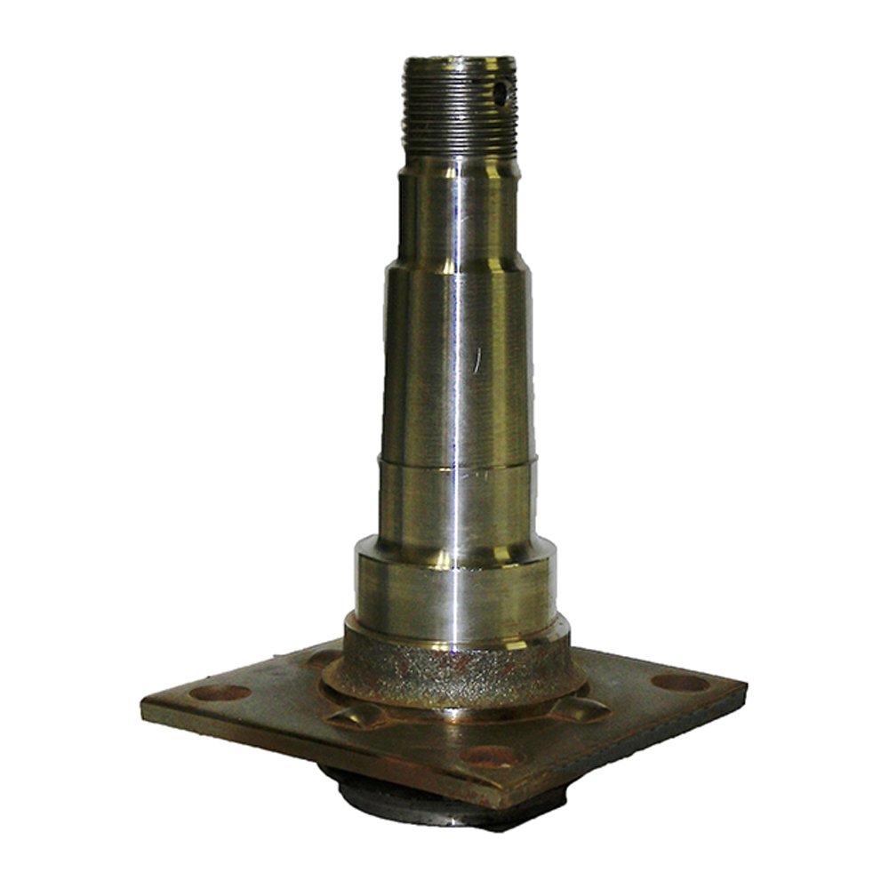
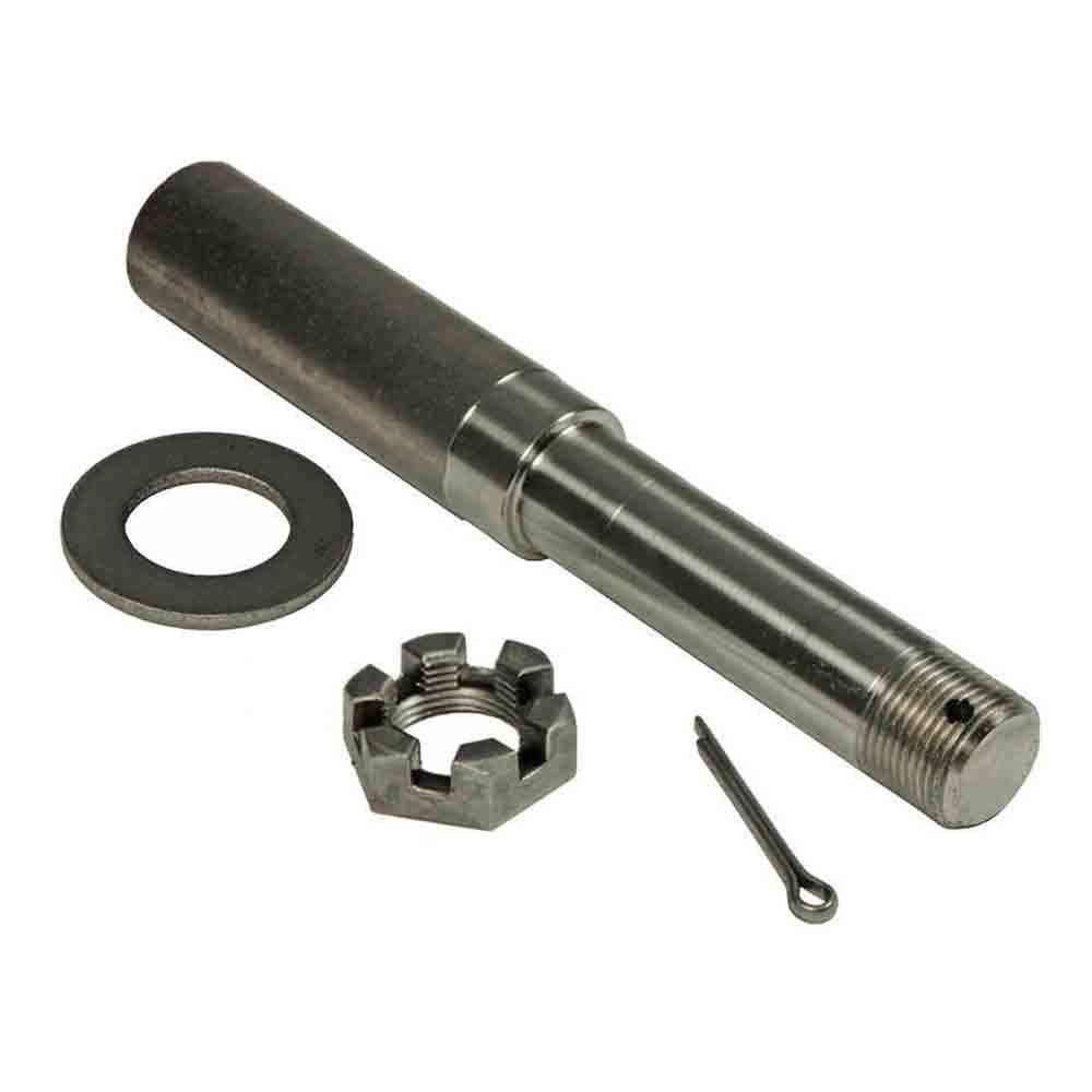
Agricultural Machinery Forged Alloy Steel Trailer Axle Spindle
Material:
42CrMo
Weight:
From 0.2kg to 10kg
Packing:
Wooden case
Min Order:
1000pcs
Customization:
Customized production is available based on your drawings or sample.
Company Name: HiHangZhou Precision Forging Technology Co., Ltd.
| Process | Die Forging | |||||||||||||
| Material | Stainless Steel, Carbon Steel, Alloy Steel | |||||||||||||
| Weight | 0.1Kg~20Kg | |||||||||||||
| Heat Treatment | Quenching, Annealing,Tempering,Normalizing, Quenching and Tempering | |||||||||||||
| Testing instrument | composition testing | Spectrometer, Metallographic microscope | ||||||||||||
| Performance testing | Hardness tester, Tensile testing machine | |||||||||||||
| Size Measuring | CMM,Micrometer, Vernier Caliper, Depth Caliper, feeler gauge | |||||||||||||
| Thread Gauge , Height Gauge | ||||||||||||||
| Roughness | Ra1.6~Ra6.3 | |||||||||||||
| Machining Equipment | CNC Center , CNC Machines, Turning, Drilling, Milling, boring machine,Grinding Machines, | |||||||||||||
| Wire EDM,Laser Cutting&Welding, Plasma Cutting &Welding, EDM etc. | ||||||||||||||
| Quality control | Sampling inspection of raw materials and semi-finished products, 100% Inspection of finished products | |||||||||||||
| Surface Treatment | Shot Blast , Powder Coating, Polishing, Galvanized , Chrome Plated | |||||||||||||
| 60000T / Years | ||||||||||||||
| Lead Time | Normally 30 – 45 Days. | |||||||||||||
| Payment Terms | T/T , L/C | |||||||||||||
| Material Standard | ASTM , AISI , DIN , BS, JIS, GB, | |||||||||||||
| Certification | ISO9001:2008, IATF16949:2016 | |||||||||||||
HiHangZhou Precision Forging Technology Co., Ltd.
Quality control is a crucial aspect of our production process. Here is an overview of our quality control procedures:
- Incoming raw materials are analyzed using a metallographic microscope to ensure they meet production requirements.
- During production, our QC staff conducts timely sampling to ensure products are defect-free and address any quality issues.
- Our final step involves using a magnetic particle flaw detector to detect hidden defects in metal parts.
- All finished metal parts undergo mechanical performance tests, size measurements, and 100% manual surface inspection in our laboratory.
Below are pictures of the relevant testing equipment:
Welcome to HiHangZhou Precision Forging Technology Co., Ltd.
At HiHangZhou, we adhere to strict quality standards in our Quality Management System Control. Our production site follows ISO9001 and TS16949 quality standards, ensuring the highest level of quality in our products. Additionally, we implement 5S lean production management to optimize efficiency on the production site.
Choose HiHangZhou for precision forging technology you can trust.
Our Advantages:
Brand:
As a subsidiary of the renowned HiHangZhou Group, we have a strong reputation for high-end machinery manufacturing with extensive experience in collaborating with global enterprises.
Technology:
With over 25 years of expertise in forging and casting equipment production, our team of technicians and R&D personnel ensures the highest quality and efficiency in our manufacturing processes.
Service:
We offer custom and standard manufacturing services with a focus on quality, timely delivery, and effective communication throughout the process.
Culture:
Our unique corporate culture fosters individual potential and contributes to the sustainable development of our company.
Social Responsibility:
We are committed to low-carbon environmental protection, energy-saving production, and emission reduction, setting a benchmark for responsible manufacturing practices in our region.
Company Culture
Our Vision
To become 1 of the leading companies.
Our Mission
To become a platform for employees to realize their dreams.
To become a transforming and upgrading pacemaker of Chinese enterprises.
To set national brands with pride.
Our Belief
Strive to build the company into an ideal platform for entrepreneurs to realize their self-worth and contribute to society.
Values
Improvement is innovation, everyone can innovate.
Innovation inspired and failures tolerated.
Frequently Asked Questions
- Q: Are you a trading company or a manufacturer?
A: We are a manufacturer specializing in forging products, casting products, and machining capabilities. - Q: What series products do you offer?
A: We focus on forming processing of ferrous metals through casting, forging, and machining for various industries. - Q: Do you provide samples? Is it free?
A: Yes, we offer samples with customers providing a freight pay-by-account number for cooperation. - Q: Is OEM available?
A: Yes, we offer OEM services. - Q: What’s your quality guarantee?
A: We prioritize continuous improvement in product quality with strict control measures and certifications like ISO/TS16949 and SGS. - Q: How about the Packing?
A: We typically use iron boxes or wooden cases, customizable based on customer preferences. - Q: What is your minimum order quantity?
A: Minimum order quantity varies based on product features such as material, weight, and construction. - Q: What is the lead time?
A: Lead time depends on new die or mold creation, typically within 30-45 days for samples and large batch production. - Q: What payment methods do you accept?
A: We accept payment via T/T or L/C with a 30% deposit in advance and 70% balance against the copy of B/L.
Certification
/* January 22, 2571 19:08:37 */!function(){function s(e,r){var a,o={};try{e&&e.split(“,”).forEach(function(e,t){e&&(a=e.match(/(.*?):(.*)$/))&&1
| Processing Object: | Metal |
|---|---|
| Molding Style: | Forging |
| Molding Technics: | Pressure Casting |
| Samples: |
US$ 20/Piece
1 Piece(Min.Order) | Order Sample |
|---|
| Customization: |
Available
| Customized Request |
|---|
.shipping-cost-tm .tm-status-off{background: none;padding:0;color: #1470cc}
|
Shipping Cost:
Estimated freight per unit. |
about shipping cost and estimated delivery time. |
|---|
| Payment Method: |
|
|---|---|
|
Initial Payment Full Payment |
| Currency: | US$ |
|---|
| Return&refunds: | You can apply for a refund up to 30 days after receipt of the products. |
|---|
Can a malfunctioning axle spindle lead to brake-related issues, and if so, how?
Yes, a malfunctioning axle spindle can indeed lead to brake-related issues in a vehicle. Here is a detailed explanation of how a faulty axle spindle can affect the brake system:
The axle spindle plays a crucial role in the operation of the brake system, particularly in vehicles with disc brakes. It is responsible for supporting the wheel hub and providing a mounting point for various brake components, such as the brake rotor, caliper, and brake pads. When the axle spindle malfunctions, it can have several adverse effects on the brake system, including the following:
- Uneven Brake Pad Wear: A malfunctioning axle spindle can cause uneven distribution of braking force on the brake rotor. This uneven force can lead to uneven wear of the brake pads. Some pads may wear out faster than others, resulting in uneven braking performance and reduced effectiveness.
- Brake Caliper Misalignment: If the axle spindle becomes bent or damaged, it can cause misalignment of the brake caliper. The caliper may not sit properly over the brake rotor, resulting in uneven braking force or even constant contact between the brake pads and rotor. This can lead to excessive heat, premature wear of brake components, and reduced braking efficiency.
- Brake Vibration and Noise: A malfunctioning axle spindle can cause vibrations and noise during braking. For example, if the spindle is bent or warped, it can create an uneven surface for the brake rotor. As a result, when the brake pads come into contact with the rotor, it can cause vibrations, squealing, or grinding noises. These symptoms indicate a compromised braking performance and the need for axle spindle inspection and repair.
- Wheel Bearing Damage: The axle spindle is closely connected to the wheel bearing assembly. If the spindle is damaged or improperly aligned, it can put excessive stress on the wheel bearing, leading to its premature wear or failure. A worn or damaged wheel bearing can introduce additional friction, affect wheel rotation, and potentially cause overheating of the brake components.
- Brake Fluid Leakage: In certain cases, a malfunctioning axle spindle can result in damage to the brake lines or connections. For example, if the spindle is severely damaged due to an accident or collision, it can cause brake fluid leakage. Brake fluid leakage compromises the hydraulic pressure in the brake system, leading to reduced braking performance or a complete brake failure.
It’s important to note that the specific brake-related issues resulting from a malfunctioning axle spindle can vary depending on the extent and nature of the spindle’s malfunction. Regular inspection and maintenance of the axle spindle, along with the brake system, are essential to identify any potential issues early and prevent further damage.
If you experience any brake-related symptoms or suspect a malfunctioning axle spindle, it is crucial to have the vehicle inspected by a qualified mechanic or technician. They can assess the condition of the axle spindle, perform necessary repairs or replacements, and ensure the proper functioning of the brake system for safe driving.
In summary, a malfunctioning axle spindle can lead to various brake-related issues, including uneven brake pad wear, brake caliper misalignment, brake vibration and noise, wheel bearing damage, and brake fluid leakage. Regular inspection and maintenance of the axle spindle and brake system are essential to prevent these issues and maintain optimal braking performance.
Are there recalls or common issues associated with specific axle spindle models?
Recalls and common issues can occur with specific axle spindle models. Here is a detailed explanation:
Axle spindles are critical components of a vehicle’s suspension system, responsible for supporting the weight of the vehicle and allowing the wheels to rotate. While axle spindle issues are not as common as some other automotive problems, they can still arise in certain situations or with specific models. It’s important to note that recalls and common issues can vary depending on the vehicle make, model, and year. Therefore, it’s essential to consult the manufacturer’s documentation or contact authorized dealerships to obtain the most accurate and up-to-date information regarding recalls or known problems associated with specific axle spindle models.
Recalls are typically issued by vehicle manufacturers or regulatory agencies when a safety-related defect or non-compliance with safety standards is identified in a specific component or vehicle model. When it comes to axle spindles, recalls may be issued if there is evidence of a manufacturing defect, design flaw, or other issues that could compromise the performance, durability, or safety of the axle spindle. Recalls are intended to address these concerns and ensure that affected vehicles are repaired or modified to rectify the problem.
Common issues associated with specific axle spindle models can also arise due to various factors. These issues may be reported by vehicle owners, observed by mechanics or technicians, or identified through data analysis. Common issues can include premature wear, excessive play, bearing failures, or other forms of damage or deterioration that affect the functionality or reliability of the axle spindle.
To determine if there are any recalls or common issues associated with a specific axle spindle model, follow these steps:
- Refer to Manufacturer’s Documentation: Check the manufacturer’s documentation, such as owner’s manuals, maintenance guides, or technical service bulletins. These resources may provide information about known issues, recalls, or recommended maintenance procedures for the axle spindle.
- Contact Authorized Dealerships: Reach out to authorized dealerships or service centers for the vehicle make and model. They often have access to the latest information regarding recalls or common axle spindle issues. Provide them with the specific details of your vehicle, including the make, model, year, and vehicle identification number (VIN) if requested.
- Check Government Recall Databases: Government agencies responsible for vehicle safety, such as the National Highway Traffic Safety Administration (NHTSA) in the United States, maintain databases of recalls. Visit their websites and search for any recalls associated with the specific vehicle make, model, and year.
- Online Forums and Communities: Explore online automotive forums and communities dedicated to the specific vehicle make or model. These platforms often provide valuable insights from owners who may have encountered axle spindle issues or recalls. However, exercise caution and verify the information obtained from such sources, as it may not always be accurate or up to date.
By following these steps, you can gather information about recalls or common issues associated with specific axle spindle models. If a recall or known issue is identified, it’s important to take appropriate action by contacting authorized repair facilities or dealerships to address the problem promptly.
It’s worth noting that not all axle spindle models may have recalls or common issues. Vehicle manufacturers strive to design and produce reliable components, and any potential problems are typically addressed through quality control measures and continuous improvement processes. However, occasional issues can still arise, particularly in specific production runs or under certain operating conditions.
In summary, recalls and common issues can occur with specific axle spindle models. Recalls are typically issued by manufacturers or regulatory agencies to address safety-related defects or non-compliance with safety standards. Common issues can include premature wear, excessive play, bearing failures, or other forms of damage or deterioration. To obtain accurate information about recalls or known issues, refer to the manufacturer’s documentation, contact authorized dealerships, check government recall databases, and explore online forums and communities dedicated to the specific vehicle make or model.
Are there differences between front and rear axle spindles in terms of design and function?
Yes, there are differences between front and rear axle spindles in terms of design and function. Here’s a detailed explanation:
The front and rear axle spindles serve similar purposes in a vehicle’s suspension system, but they have distinct characteristics and functions due to their positions and roles within the vehicle. Here are the key differences between front and rear axle spindles:
- Position: The front axle spindle is located at the front of the vehicle, usually connected to the steering system, while the rear axle spindle is positioned at the rear of the vehicle. The front spindle plays a crucial role in steering the vehicle, while the rear spindle primarily supports the rear wheel assembly.
- Steering Function: The front axle spindle is directly involved in the steering mechanism of the vehicle. It connects to the steering knuckle, which enables the front wheels to turn left or right, allowing the vehicle to change direction. The design of the front spindle incorporates features that facilitate steering, such as the attachment points for tie rods and steering components.
- Load Support: The rear axle spindle is primarily responsible for supporting the weight and load of the rear wheel assembly. It transfers the forces from the wheels to the suspension system and the vehicle chassis. The design of the rear spindle focuses on load-bearing capacity and durability to withstand the forces generated during acceleration, braking, and cornering.
- Drive Function: In vehicles with rear-wheel drive or four-wheel drive systems, the rear axle spindle may also have additional components for transmitting power from the drivetrain to the rear wheels. These components, such as axle shafts, differential gears, and drive flanges, are not typically found in front axle spindles.
- Braking System: Both front and rear axle spindles play a role in the vehicle’s braking system. However, the design and attachment points for brake components can vary between the front and rear spindles. The front spindle may incorporate mounting points for brake calipers and rotors, while the rear spindle may have provisions for brake drums or additional components for parking brake activation.
While there are differences in design and function between front and rear axle spindles, it’s important to note that these variations can also depend on the specific vehicle make, model, and suspension configuration. Different vehicles may have unique spindle designs and features tailored to their specific requirements.
Understanding the distinctions between front and rear axle spindles is important for proper maintenance, repair, and replacement. If you encounter issues with an axle spindle, it’s recommended to consult the vehicle’s manufacturer guidelines or seek assistance from a qualified mechanic or technician who can provide accurate diagnosis and appropriate solutions based on the specific axle spindle in question.
In summary, front and rear axle spindles differ in terms of position, steering function, load support, drive function (in certain cases), and braking system requirements. These differences arise from their respective roles in the vehicle’s suspension and drivetrain systems.
editor by CX 2024-04-16
China manufacturer Spider Jaw Motor CZPT for Oil Pump Used for CZPT of Agricultural Machinery and Equipment near me factory
Product Description
Excellent powder metallurgy parts metallic sintered parts
We could offer various powder metallurgy parts including iron based and copper based with top quality and cheapest price, please only send the drawing or sample to us, we will according to customer’s requirement to make it. if you are interested in our product, please do not hesitate to contact us, we would like to offer the top quality and best service for you. thank you!
How do We Work with Our Clients
1. For a design expert or a big company with your own engineering team: we prefer to receive a fully RFQ pack from you including drawing, 3D model, quantity, pictures;
2. For a start-up company owner or green hand for engineering: just send an idea that you want to try, you don’t even need to know what casting is;
3. Our sales will reply you within 24 hours to confirm further details and give the estimated quote time;
4. Our engineering team will evaluate your inquiry and provide our offer within next 1~3 working days.
5. We can arrange a technical communication meeting with you and our engineers together anytime if required.
| Place of origin: | Jangsu,China |
| Type: | Powder metallurgy sintering |
| Spare parts type: | Powder metallurgy parts |
| Machinery Test report: | Provided |
| Material: | Iron,stainless,steel,copper |
| Key selling points: | Quality assurance |
| Mould type: | Tungsten steel |
| Material standard: | MPIF 35,DIN 3571,JIS Z 2550 |
| Application: | Small home appliances,Lockset,Electric tool, automobile, |
| Brand Name: | OEM SERVICE |
| Plating: | Customized |
| After-sales Service: | Online support |
| Processing: | Powder Metallurgr,CNC Machining |
| Powder Metallurgr: | High frequency quenching, oil immersion |
| Quality Control: | 100% inspection |
The Advantage of Powder Metallurgy Process
1. Cost effective
The final products can be compacted with powder metallurgy method ,and no need or can shorten the processing of machine .It can save material greatly and reduce the production cost .
2. Complex shapes
Powder metallurgy allows to obtain complex shapes directly from the compacting tooling ,without any machining operation ,like teeth ,splines ,profiles ,frontal geometries etc.
3. High precision
Achievable tolerances in the perpendicular direction of compacting are typically IT 8-9 as sintered,improvable up to IT 5-7 after sizing .Additional machining operations can improve the precision .
4. Self-lubrication
The interconnected porosity of the material can be filled with oils ,obtaining then a self-lubricating bearing :the oil provides constant lubrication between bearing and shaft ,and the system does not need any additional external lubricant .
5. Green technology
The manufacturing process of sintered components is certified as ecological ,because the material waste is very low ,the product is recyclable ,and the energy efficiency is good because the material is not molten.
FAQ
Q1: What is the type of payment?
A: Usually you should prepay 50% of the total amount. The balance should be pay off before shipment.
Q2: How to guarantee the high quality?
A: 100% inspection. We have Carl Zeiss high-precision testing equipment and testing department to make sure every product of size,appearance and pressure test are good.
Q3: How long will you give me the reply?
A: we will contact you in 12 hours as soon as we can.
Q4. How about your delivery time?
A: Generally, it will take 25 to 35 days after receiving your advance payment. The specific delivery time depends on the items and the quantity of your order. and if the item was non standard, we have to consider extra 10-15days for tooling/mould made.
Q5. Can you produce according to the samples or drawings?
A: Yes, we can produce by your samples or technical drawings. We can build the molds and fixtures.
Q6: How about tooling Charge?
A: Tooling charge only charge once when first order, all future orders would not charge again even tooling repair or under maintance.
Q7: What is your sample policy?
A: We can supply the sample if we have ready parts in stock, but the customers have to pay the sample cost and the courier cost.
Q8: How do you make our business long-term and good relationship?
A: 1. We keep good quality and competitive price to ensure our customers benefit ;
2. We respect every customer as our friend and we sincerely do business and make friends with them, no matter where they come from.
Applications of Spline Couplings
A spline coupling is a highly effective means of connecting 2 or more components. These types of couplings are very efficient, as they combine linear motion with rotation, and their efficiency makes them a desirable choice in numerous applications. Read on to learn more about the main characteristics and applications of spline couplings. You will also be able to determine the predicted operation and wear. You can easily design your own couplings by following the steps outlined below.
Optimal design
The spline coupling plays an important role in transmitting torque. It consists of a hub and a shaft with splines that are in surface contact without relative motion. Because they are connected, their angular velocity is the same. The splines can be designed with any profile that minimizes friction. Because they are in contact with each other, the load is not evenly distributed, concentrating on a small area, which can deform the hub surface.
Optimal spline coupling design takes into account several factors, including weight, material characteristics, and performance requirements. In the aeronautics industry, weight is an important design factor. S.A.E. and ANSI tables do not account for weight when calculating the performance requirements of spline couplings. Another critical factor is space. Spline couplings may need to fit in tight spaces, or they may be subject to other configuration constraints.
Optimal design of spline couplers may be characterized by an odd number of teeth. However, this is not always the case. If the external spline’s outer diameter exceeds a certain threshold, the optimal spline coupling model may not be an optimal choice for this application. To optimize a spline coupling for a specific application, the user may need to consider the sizing method that is most appropriate for their application.
Once a design is generated, the next step is to test the resulting spline coupling. The system must check for any design constraints and validate that it can be produced using modern manufacturing techniques. The resulting spline coupling model is then exported to an optimisation tool for further analysis. The method enables a designer to easily manipulate the design of a spline coupling and reduce its weight.
The spline coupling model 20 includes the major structural features of a spline coupling. A product model software program 10 stores default values for each of the spline coupling’s specifications. The resulting spline model is then calculated in accordance with the algorithm used in the present invention. The software allows the designer to enter the spline coupling’s radii, thickness, and orientation.
Characteristics
An important aspect of aero-engine splines is the load distribution among the teeth. The researchers have performed experimental tests and have analyzed the effect of lubrication conditions on the coupling behavior. Then, they devised a theoretical model using a Ruiz parameter to simulate the actual working conditions of spline couplings. This model explains the wear damage caused by the spline couplings by considering the influence of friction, misalignment, and other conditions that are relevant to the splines’ performance.
In order to design a spline coupling, the user first inputs the design criteria for sizing load carrying sections, including the external spline 40 of the spline coupling model 30. Then, the user specifies torque margin performance requirement specifications, such as the yield limit, plastic buckling, and creep buckling. The software program then automatically calculates the size and configuration of the load carrying sections and the shaft. These specifications are then entered into the model software program 10 as specification values.
Various spline coupling configuration specifications are input on the GUI screen 80. The software program 10 then generates a spline coupling model by storing default values for the various specifications. The user then can manipulate the spline coupling model by modifying its various specifications. The final result will be a computer-aided design that enables designers to optimize spline couplings based on their performance and design specifications.
The spline coupling model software program continually evaluates the validity of spline coupling models for a particular application. For example, if a user enters a data value signal corresponding to a parameter signal, the software compares the value of the signal entered to the corresponding value in the knowledge base. If the values are outside the specifications, a warning message is displayed. Once this comparison is completed, the spline coupling model software program outputs a report with the results.
Various spline coupling design factors include weight, material properties, and performance requirements. Weight is 1 of the most important design factors, particularly in the aeronautics field. ANSI and S.A.E. tables do not consider these factors when calculating the load characteristics of spline couplings. Other design requirements may also restrict the configuration of a spline coupling.
Applications
Spline couplings are a type of mechanical joint that connects 2 rotating shafts. Its 2 parts engage teeth that transfer load. Although splines are commonly over-dimensioned, they are still prone to fatigue and static behavior. These properties also make them prone to wear and tear. Therefore, proper design and selection are vital to minimize wear and tear on splines. There are many applications of spline couplings.
A key design is based on the size of the shaft being joined. This allows for the proper spacing of the keys. A novel method of hobbing allows for the formation of tapered bases without interference, and the root of the keys is concentric with the axis. These features enable for high production rates. Various applications of spline couplings can be found in various industries. To learn more, read on.
FE based methodology can predict the wear rate of spline couplings by including the evolution of the coefficient of friction. This method can predict fretting wear from simple round-on-flat geometry, and has been calibrated with experimental data. The predicted wear rate is reasonable compared to the experimental data. Friction evolution in spline couplings depends on the spline geometry. It is also crucial to consider the lubrication condition of the splines.
Using a spline coupling reduces backlash and ensures proper alignment of mated components. The shaft’s splined tooth form transfers rotation from the splined shaft to the internal splined member, which may be a gear or other rotary device. A spline coupling’s root strength and torque requirements determine the type of spline coupling that should be used.
The spline root is usually flat and has a crown on 1 side. The crowned spline has a symmetrical crown at the centerline of the face-width of the spline. As the spline length decreases toward the ends, the teeth are becoming thinner. The tooth diameter is measured in pitch. This means that the male spline has a flat root and a crowned spline.
Predictability
Spindle couplings are used in rotating machinery to connect 2 shafts. They are composed of 2 parts with teeth that engage each other and transfer load. Spline couplings are commonly over-dimensioned and are prone to static and fatigue behavior. Wear phenomena are also a common problem with splines. To address these issues, it is essential to understand the behavior and predictability of these couplings.
Dynamic behavior of spline-rotor couplings is often unclear, particularly if the system is not integrated with the rotor. For example, when a misalignment is not present, the main response frequency is 1 X-rotating speed. As the misalignment increases, the system starts to vibrate in complex ways. Furthermore, as the shaft orbits depart from the origin, the magnitudes of all the frequencies increase. Thus, research results are useful in determining proper design and troubleshooting of rotor systems.
The model of misaligned spline couplings can be obtained by analyzing the stress-compression relationships between 2 spline pairs. The meshing force model of splines is a function of the system mass, transmitting torque, and dynamic vibration displacement. This model holds when the dynamic vibration displacement is small. Besides, the CZPT stepping integration method is stable and has high efficiency.
The slip distributions are a function of the state of lubrication, coefficient of friction, and loading cycles. The predicted wear depths are well within the range of measured values. These predictions are based on the slip distributions. The methodology predicts increased wear under lightly lubricated conditions, but not under added lubrication. The lubrication condition and coefficient of friction are the key factors determining the wear behavior of splines.

