Product Description
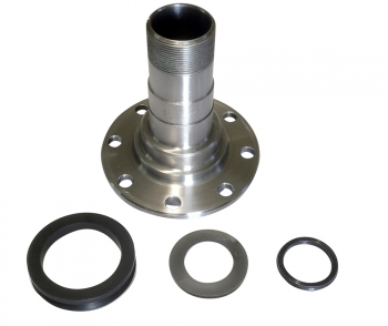
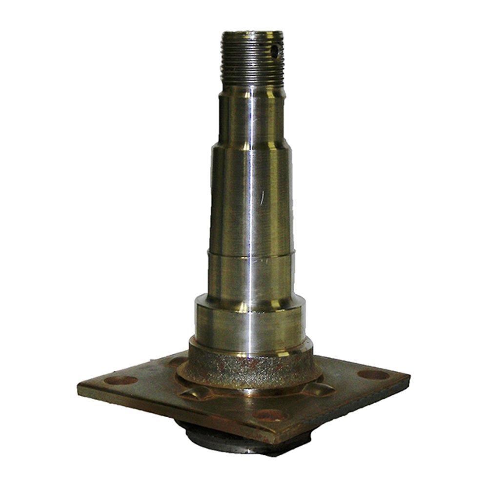
Forged Wind Power Spindle for Wind Power Equipment Forgings Machinery Part
Products Show
Factory
Inspection
Certifications
| Description | CUSTOM MADE PRECISION CASTINGS |
| Material | (1)grey iron, ductile iron , pig iron (2)carbon steel, stainless steel, alloy steel (3)aluminum alloy, aluminum, A380, aluminum 6061 (4)zinc alloy ,copper, brass, bronze etc |
| Standard | ISO ,DIN, AISI, ASTM, BS, JIS, etc. |
| Size | Available in all sizes or as customer’s drawings |
| Certification | ISO9001:2008 |
| Application | Industrial parts, Machinery parts, construction parts, valve parts, train, craft, hydraulic pressure, Agricultural machinery, Marine hardware, Auto parts, electric power fittings, food machinery, harness fittings, tools, mining machinery parts |
| Weight Range | 0.01kg-200kg |
| Machining precision | ±0.01mm |
| Surface Treatment | Heat Treatment, Polishing, Plating, Machining, Anodizing, shot, sand blasting, zinc plated, oxide, galvanized etc. |
| Process | Lost wax casting process, die casting process, sand casting process. Soluble glass casting process, silicasol casting process |
| Production Application | Metal parts, Mechanical parts, Marine Hardware, Electric power fitting, Construction parts, Pipe Fitting, Hardware, Auto parts, Valve parts, Industrial parts, Agricultural machinery, Hinges, etc |
| CNC and MC machining | Three coordinate measurement machine for testing. |
| Service | To chart to sample production; OEM / ODM |
| Packing details | Wood or carton packages as per your demands |
| MOQ | 500 pieces (Small order is accepted) |
| Material: | Carbon Steel |
|---|---|
| Load: | Drive Shaft |
| Stiffness & Flexibility: | Stiffness / Rigid Axle |
| Journal Diameter Dimensional Accuracy: | IT01-IT5 |
| Axis Shape: | Straight Shaft |
| Shaft Shape: | Stepped Shaft |
| Customization: |
Available
| Customized Request |
|---|
Where can I find reliable resources for learning about axle spindle maintenance and repair?
If you’re looking to learn about axle spindle maintenance and repair, there are several reliable resources available to help you gain the necessary knowledge and skills. Here’s a detailed explanation of where you can find such resources:
- Vehicle Manufacturer’s Official Documentation: One of the best sources of information for axle spindle maintenance and repair is the official documentation provided by the vehicle manufacturer. This includes the vehicle’s owner’s manual, service manual, or technical guides. These resources often contain detailed instructions, diagrams, torque specifications, and other relevant information specific to your vehicle make, model, and year.
- Automotive Repair Manuals: There are various reputable automotive repair manuals available in the market. These manuals, such as those published by Haynes or Chilton, provide comprehensive guides for vehicle maintenance and repair. They often cover a wide range of topics, including axle spindle maintenance and repair, with step-by-step instructions, illustrations, and troubleshooting tips.
- Online Repair Guides and Websites: The internet offers a wealth of information on automotive maintenance and repair. Websites such as AutoZone, RepairPal, and iFixit provide detailed repair guides, tutorials, and forums where you can find information specific to axle spindle maintenance and repair. Additionally, online forums and communities dedicated to automotive enthusiasts can be valuable resources for learning from experienced individuals and seeking advice.
- YouTube Video Tutorials: YouTube is a popular platform for instructional videos, and you can find numerous video tutorials related to axle spindle maintenance and repair. Many automotive enthusiasts, mechanics, and professional technicians create informative videos demonstrating the procedures, tools, and techniques involved in working on axle spindles. These videos often provide visual demonstrations that can be helpful for understanding the repair process.
- Local Libraries and Bookstores: Your local library or bookstore may have a selection of automotive repair books and manuals that cover axle spindle maintenance and repair. These resources can be valuable references for learning about the topic in a more comprehensive and in-depth manner.
- Professional Mechanics and Technicians: If you have access to professional mechanics or technicians, they can be excellent resources for learning about axle spindle maintenance and repair. They possess hands-on experience and expert knowledge in the field. You can seek their guidance, ask questions, and even observe them during the repair process to gain practical insights and tips.
When utilizing these resources, it’s important to cross-reference information and ensure that you’re consulting reputable sources. Always prioritize information from reliable and trusted sources, such as official documentation, reputable repair manuals, and established automotive websites or experts.
Learning about axle spindle maintenance and repair requires a combination of theoretical knowledge and practical experience. It’s recommended to start with the basics, familiarize yourself with the terminology, and gradually progress to more advanced topics. Take your time, follow safety precautions, and be prepared to seek professional assistance when necessary.
In summary, reliable resources for learning about axle spindle maintenance and repair can be found in various forms, including vehicle manufacturer’s official documentation, automotive repair manuals, online repair guides and websites, YouTube video tutorials, local libraries and bookstores, and professional mechanics and technicians. By utilizing these resources, you can enhance your understanding and skills in maintaining and repairing axle spindles effectively.
Are there recalls or common issues associated with specific axle spindle models?
Recalls and common issues can occur with specific axle spindle models. Here is a detailed explanation:
Axle spindles are critical components of a vehicle’s suspension system, responsible for supporting the weight of the vehicle and allowing the wheels to rotate. While axle spindle issues are not as common as some other automotive problems, they can still arise in certain situations or with specific models. It’s important to note that recalls and common issues can vary depending on the vehicle make, model, and year. Therefore, it’s essential to consult the manufacturer’s documentation or contact authorized dealerships to obtain the most accurate and up-to-date information regarding recalls or known problems associated with specific axle spindle models.
Recalls are typically issued by vehicle manufacturers or regulatory agencies when a safety-related defect or non-compliance with safety standards is identified in a specific component or vehicle model. When it comes to axle spindles, recalls may be issued if there is evidence of a manufacturing defect, design flaw, or other issues that could compromise the performance, durability, or safety of the axle spindle. Recalls are intended to address these concerns and ensure that affected vehicles are repaired or modified to rectify the problem.
Common issues associated with specific axle spindle models can also arise due to various factors. These issues may be reported by vehicle owners, observed by mechanics or technicians, or identified through data analysis. Common issues can include premature wear, excessive play, bearing failures, or other forms of damage or deterioration that affect the functionality or reliability of the axle spindle.
To determine if there are any recalls or common issues associated with a specific axle spindle model, follow these steps:
- Refer to Manufacturer’s Documentation: Check the manufacturer’s documentation, such as owner’s manuals, maintenance guides, or technical service bulletins. These resources may provide information about known issues, recalls, or recommended maintenance procedures for the axle spindle.
- Contact Authorized Dealerships: Reach out to authorized dealerships or service centers for the vehicle make and model. They often have access to the latest information regarding recalls or common axle spindle issues. Provide them with the specific details of your vehicle, including the make, model, year, and vehicle identification number (VIN) if requested.
- Check Government Recall Databases: Government agencies responsible for vehicle safety, such as the National Highway Traffic Safety Administration (NHTSA) in the United States, maintain databases of recalls. Visit their websites and search for any recalls associated with the specific vehicle make, model, and year.
- Online Forums and Communities: Explore online automotive forums and communities dedicated to the specific vehicle make or model. These platforms often provide valuable insights from owners who may have encountered axle spindle issues or recalls. However, exercise caution and verify the information obtained from such sources, as it may not always be accurate or up to date.
By following these steps, you can gather information about recalls or common issues associated with specific axle spindle models. If a recall or known issue is identified, it’s important to take appropriate action by contacting authorized repair facilities or dealerships to address the problem promptly.
It’s worth noting that not all axle spindle models may have recalls or common issues. Vehicle manufacturers strive to design and produce reliable components, and any potential problems are typically addressed through quality control measures and continuous improvement processes. However, occasional issues can still arise, particularly in specific production runs or under certain operating conditions.
In summary, recalls and common issues can occur with specific axle spindle models. Recalls are typically issued by manufacturers or regulatory agencies to address safety-related defects or non-compliance with safety standards. Common issues can include premature wear, excessive play, bearing failures, or other forms of damage or deterioration. To obtain accurate information about recalls or known issues, refer to the manufacturer’s documentation, contact authorized dealerships, check government recall databases, and explore online forums and communities dedicated to the specific vehicle make or model.
What is the primary role of the axle spindle in a vehicle’s suspension system?
The primary role of the axle spindle in a vehicle’s suspension system is to support and facilitate the rotation of the wheel assembly. Here’s a detailed explanation:
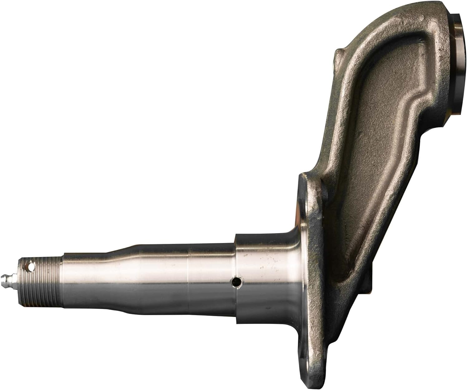
The axle spindle, also known as the wheel spindle or stub axle, is a component of the suspension system that connects the wheel hub assembly to the suspension system. It plays a crucial role in supporting the weight of the vehicle, transmitting driving forces, and allowing the wheel assembly to rotate smoothly.
Here are the primary functions and roles of the axle spindle:
- Wheel Mounting: The axle spindle provides a mounting point for the wheel hub assembly. It typically extends from the steering knuckle or axle beam and incorporates a flange or hub surface where the wheel is mounted. The spindle ensures proper alignment and secure attachment of the wheel to the suspension system.
- Load Support: One of the main responsibilities of the axle spindle is to support the weight of the vehicle and any additional loads. It transfers the vertical load from the wheel assembly to the suspension system and ultimately to the vehicle chassis. The spindle should be designed to withstand the weight and forces encountered during normal driving conditions.
- Wheel Rotation: The axle spindle allows the wheel assembly to rotate freely. It acts as an axle or pivot point around which the wheel rotates when the vehicle is in motion. The spindle is typically designed with a smooth, cylindrical shape that fits into the wheel bearings, allowing for low-friction rotation.
- Steering Function: In some suspension systems, particularly those with steering knuckles, the axle spindle also plays a role in the steering function. It connects to the steering linkage or tie rods, allowing for the controlled movement of the wheel assembly during steering maneuvers. The spindle’s design and attachment points should facilitate the proper functioning of the steering system.
- Transmission of Forces: The axle spindle transmits driving and braking forces from the wheel assembly to the suspension system. These forces include torque from the engine during acceleration and braking forces when the brakes are applied. The spindle should be able to handle these forces without failure or excessive deflection.
It’s important to note that the design and construction of axle spindles can vary depending on the specific suspension system used in a vehicle. Different suspension types, such as independent suspension or solid axle suspension, may have variations in spindle design and attachment methods. Additionally, the axle spindle must be properly lubricated and maintained to ensure smooth operation and longevity.
In summary, the primary role of the axle spindle in a vehicle’s suspension system is to support and facilitate the rotation of the wheel assembly. It provides a mounting point for the wheel hub assembly, supports the vehicle’s weight, allows for wheel rotation, contributes to the steering function, and transmits driving forces. The design and construction of the axle spindle may vary depending on the suspension system used in the vehicle.


editor by CX 2023-11-16
China manufacturer Spider Jaw Motor CZPT for Oil Pump Used for CZPT of Agricultural Machinery and Equipment near me factory
Product Description
Excellent powder metallurgy parts metallic sintered parts
We could offer various powder metallurgy parts including iron based and copper based with top quality and cheapest price, please only send the drawing or sample to us, we will according to customer’s requirement to make it. if you are interested in our product, please do not hesitate to contact us, we would like to offer the top quality and best service for you. thank you!
How do We Work with Our Clients
1. For a design expert or a big company with your own engineering team: we prefer to receive a fully RFQ pack from you including drawing, 3D model, quantity, pictures;
2. For a start-up company owner or green hand for engineering: just send an idea that you want to try, you don’t even need to know what casting is;
3. Our sales will reply you within 24 hours to confirm further details and give the estimated quote time;
4. Our engineering team will evaluate your inquiry and provide our offer within next 1~3 working days.
5. We can arrange a technical communication meeting with you and our engineers together anytime if required.
| Place of origin: | Jangsu,China |
| Type: | Powder metallurgy sintering |
| Spare parts type: | Powder metallurgy parts |
| Machinery Test report: | Provided |
| Material: | Iron,stainless,steel,copper |
| Key selling points: | Quality assurance |
| Mould type: | Tungsten steel |
| Material standard: | MPIF 35,DIN 3571,JIS Z 2550 |
| Application: | Small home appliances,Lockset,Electric tool, automobile, |
| Brand Name: | OEM SERVICE |
| Plating: | Customized |
| After-sales Service: | Online support |
| Processing: | Powder Metallurgr,CNC Machining |
| Powder Metallurgr: | High frequency quenching, oil immersion |
| Quality Control: | 100% inspection |
The Advantage of Powder Metallurgy Process
1. Cost effective
The final products can be compacted with powder metallurgy method ,and no need or can shorten the processing of machine .It can save material greatly and reduce the production cost .
2. Complex shapes
Powder metallurgy allows to obtain complex shapes directly from the compacting tooling ,without any machining operation ,like teeth ,splines ,profiles ,frontal geometries etc.
3. High precision
Achievable tolerances in the perpendicular direction of compacting are typically IT 8-9 as sintered,improvable up to IT 5-7 after sizing .Additional machining operations can improve the precision .
4. Self-lubrication
The interconnected porosity of the material can be filled with oils ,obtaining then a self-lubricating bearing :the oil provides constant lubrication between bearing and shaft ,and the system does not need any additional external lubricant .
5. Green technology
The manufacturing process of sintered components is certified as ecological ,because the material waste is very low ,the product is recyclable ,and the energy efficiency is good because the material is not molten.
FAQ
Q1: What is the type of payment?
A: Usually you should prepay 50% of the total amount. The balance should be pay off before shipment.
Q2: How to guarantee the high quality?
A: 100% inspection. We have Carl Zeiss high-precision testing equipment and testing department to make sure every product of size,appearance and pressure test are good.
Q3: How long will you give me the reply?
A: we will contact you in 12 hours as soon as we can.
Q4. How about your delivery time?
A: Generally, it will take 25 to 35 days after receiving your advance payment. The specific delivery time depends on the items and the quantity of your order. and if the item was non standard, we have to consider extra 10-15days for tooling/mould made.
Q5. Can you produce according to the samples or drawings?
A: Yes, we can produce by your samples or technical drawings. We can build the molds and fixtures.
Q6: How about tooling Charge?
A: Tooling charge only charge once when first order, all future orders would not charge again even tooling repair or under maintance.
Q7: What is your sample policy?
A: We can supply the sample if we have ready parts in stock, but the customers have to pay the sample cost and the courier cost.
Q8: How do you make our business long-term and good relationship?
A: 1. We keep good quality and competitive price to ensure our customers benefit ;
2. We respect every customer as our friend and we sincerely do business and make friends with them, no matter where they come from.
Applications of Spline Couplings
A spline coupling is a highly effective means of connecting 2 or more components. These types of couplings are very efficient, as they combine linear motion with rotation, and their efficiency makes them a desirable choice in numerous applications. Read on to learn more about the main characteristics and applications of spline couplings. You will also be able to determine the predicted operation and wear. You can easily design your own couplings by following the steps outlined below.
Optimal design
The spline coupling plays an important role in transmitting torque. It consists of a hub and a shaft with splines that are in surface contact without relative motion. Because they are connected, their angular velocity is the same. The splines can be designed with any profile that minimizes friction. Because they are in contact with each other, the load is not evenly distributed, concentrating on a small area, which can deform the hub surface.
Optimal spline coupling design takes into account several factors, including weight, material characteristics, and performance requirements. In the aeronautics industry, weight is an important design factor. S.A.E. and ANSI tables do not account for weight when calculating the performance requirements of spline couplings. Another critical factor is space. Spline couplings may need to fit in tight spaces, or they may be subject to other configuration constraints.
Optimal design of spline couplers may be characterized by an odd number of teeth. However, this is not always the case. If the external spline’s outer diameter exceeds a certain threshold, the optimal spline coupling model may not be an optimal choice for this application. To optimize a spline coupling for a specific application, the user may need to consider the sizing method that is most appropriate for their application.
Once a design is generated, the next step is to test the resulting spline coupling. The system must check for any design constraints and validate that it can be produced using modern manufacturing techniques. The resulting spline coupling model is then exported to an optimisation tool for further analysis. The method enables a designer to easily manipulate the design of a spline coupling and reduce its weight.
The spline coupling model 20 includes the major structural features of a spline coupling. A product model software program 10 stores default values for each of the spline coupling’s specifications. The resulting spline model is then calculated in accordance with the algorithm used in the present invention. The software allows the designer to enter the spline coupling’s radii, thickness, and orientation.
Characteristics
An important aspect of aero-engine splines is the load distribution among the teeth. The researchers have performed experimental tests and have analyzed the effect of lubrication conditions on the coupling behavior. Then, they devised a theoretical model using a Ruiz parameter to simulate the actual working conditions of spline couplings. This model explains the wear damage caused by the spline couplings by considering the influence of friction, misalignment, and other conditions that are relevant to the splines’ performance.
In order to design a spline coupling, the user first inputs the design criteria for sizing load carrying sections, including the external spline 40 of the spline coupling model 30. Then, the user specifies torque margin performance requirement specifications, such as the yield limit, plastic buckling, and creep buckling. The software program then automatically calculates the size and configuration of the load carrying sections and the shaft. These specifications are then entered into the model software program 10 as specification values.
Various spline coupling configuration specifications are input on the GUI screen 80. The software program 10 then generates a spline coupling model by storing default values for the various specifications. The user then can manipulate the spline coupling model by modifying its various specifications. The final result will be a computer-aided design that enables designers to optimize spline couplings based on their performance and design specifications.
The spline coupling model software program continually evaluates the validity of spline coupling models for a particular application. For example, if a user enters a data value signal corresponding to a parameter signal, the software compares the value of the signal entered to the corresponding value in the knowledge base. If the values are outside the specifications, a warning message is displayed. Once this comparison is completed, the spline coupling model software program outputs a report with the results.
Various spline coupling design factors include weight, material properties, and performance requirements. Weight is 1 of the most important design factors, particularly in the aeronautics field. ANSI and S.A.E. tables do not consider these factors when calculating the load characteristics of spline couplings. Other design requirements may also restrict the configuration of a spline coupling.
Applications
Spline couplings are a type of mechanical joint that connects 2 rotating shafts. Its 2 parts engage teeth that transfer load. Although splines are commonly over-dimensioned, they are still prone to fatigue and static behavior. These properties also make them prone to wear and tear. Therefore, proper design and selection are vital to minimize wear and tear on splines. There are many applications of spline couplings.
A key design is based on the size of the shaft being joined. This allows for the proper spacing of the keys. A novel method of hobbing allows for the formation of tapered bases without interference, and the root of the keys is concentric with the axis. These features enable for high production rates. Various applications of spline couplings can be found in various industries. To learn more, read on.
FE based methodology can predict the wear rate of spline couplings by including the evolution of the coefficient of friction. This method can predict fretting wear from simple round-on-flat geometry, and has been calibrated with experimental data. The predicted wear rate is reasonable compared to the experimental data. Friction evolution in spline couplings depends on the spline geometry. It is also crucial to consider the lubrication condition of the splines.
Using a spline coupling reduces backlash and ensures proper alignment of mated components. The shaft’s splined tooth form transfers rotation from the splined shaft to the internal splined member, which may be a gear or other rotary device. A spline coupling’s root strength and torque requirements determine the type of spline coupling that should be used.
The spline root is usually flat and has a crown on 1 side. The crowned spline has a symmetrical crown at the centerline of the face-width of the spline. As the spline length decreases toward the ends, the teeth are becoming thinner. The tooth diameter is measured in pitch. This means that the male spline has a flat root and a crowned spline.
Predictability
Spindle couplings are used in rotating machinery to connect 2 shafts. They are composed of 2 parts with teeth that engage each other and transfer load. Spline couplings are commonly over-dimensioned and are prone to static and fatigue behavior. Wear phenomena are also a common problem with splines. To address these issues, it is essential to understand the behavior and predictability of these couplings.
Dynamic behavior of spline-rotor couplings is often unclear, particularly if the system is not integrated with the rotor. For example, when a misalignment is not present, the main response frequency is 1 X-rotating speed. As the misalignment increases, the system starts to vibrate in complex ways. Furthermore, as the shaft orbits depart from the origin, the magnitudes of all the frequencies increase. Thus, research results are useful in determining proper design and troubleshooting of rotor systems.
The model of misaligned spline couplings can be obtained by analyzing the stress-compression relationships between 2 spline pairs. The meshing force model of splines is a function of the system mass, transmitting torque, and dynamic vibration displacement. This model holds when the dynamic vibration displacement is small. Besides, the CZPT stepping integration method is stable and has high efficiency.
The slip distributions are a function of the state of lubrication, coefficient of friction, and loading cycles. The predicted wear depths are well within the range of measured values. These predictions are based on the slip distributions. The methodology predicts increased wear under lightly lubricated conditions, but not under added lubrication. The lubrication condition and coefficient of friction are the key factors determining the wear behavior of splines.

