Product Description
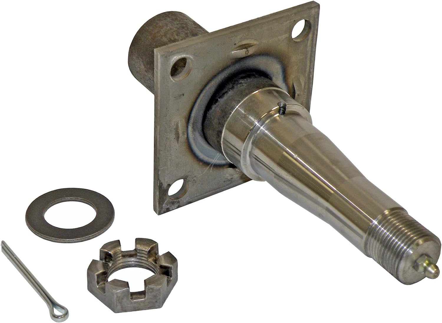
Carbon steel shaft cnc turning spindle for industrial equipment tool
Feature of CNC parts
1. Precision Cnc stainless steel parts strictly according to customer’s drawing,packing and quality request
2. Tolerance: Can be kept in +/-0.005mm
3. The most advanced CMM inspector to ensure the quality
4. Experienced technology engineers and well trained workers
5. Fast and timely delivery. Speedily&professional service
6. Give customer professional suggestion while in the process of customer designing to save costs.Our freight price is often 30-50% lower than customer’s
7. Customers can use PAYPAL and other online payment platform to pay a small amount of sample fee to shorten the sample production time
8. Quality assurance in accordance with ISO9001:2015 and ISO13485:2016
Material Available for CNC Machining
| Material | Stainless steel | SS201 SS303 SS304 SS316 17-4PH SUS440C |
| Steel | Q235 20#-45# etc | |
| Brass | C36000(C26800) C37700(HPb59) C38500(HP6 58) C27200(CuzN37)etc | |
| Iron | 1213 12L14 1215 etc | |
| Bronze | C51000 C52100 C5400etc | |
| Aluminum | Al6061 Al6063 Al7075 AL5052 etc | |
| Alloy | A2 D2 SKD11 DF2 XW/5 ASP-23 |
Terms and Conditons
| Our Processing | CNC machining, CNC milling and turning, drilling, grinding, , stamping, tapping, |
| Surface finish | Hard Coating Black Anodize Clear Anodize Hard Chrome ,Clear Zinc Plasma Niride |
| Tolerance | 0.005mm |
| QC System | 100% inspection before shipment |
| Drawing format | DWG/ IGS/ STEP/STEP,/IGES/X-T/PDF and etc. |
| Packaging | Standard package / Carton box or Pallet / As per customized specifications |
| Payment Terms | 1) Western Union for samples cost or very small order 2) 100% T/T in advance when amount less than 1000USD 3) 50% deposit, 50% balance by T/T before shipment when order amount from 3000USD to 5000USD. 4) 30% deposit, 70% balance by T/T before shipment when order amount over 5000USD. 5) L/C payment term for big amount order is acceptable. |
| Trade terms | EXW, FOB, CIF, As per customer’s request |
| Shipment Terms | 1) 0-100kg: express & air freight priority 2) >100kg: sea freight priority 3) As per customized specifications |
| Note |
All CNC machining parts are custom made according to customer’s drawings or samples, no stock.If you have any CNC machining parts to be made, please feel free to send your kind drawings/samples to us anytime by email. |
KGL Machinery&Electronics Co., Ltd.(KGL) was founded in 2013, an independent private enterprise that integrated R&D, production, sales and service.KGL is focused on CNC precision machining parts, mainly applied in the field of robotics, communications, medical, automation, and custom-designed complex parts and custom-designed equipment.The core competitiveness is rapid response capability, quality assurance system and cost control ability.We provide value-added services to customers through more technical supporting, high quality product and rapid response business processing.So customers will be more focused on their own business and thus enhance customer value.
KGL Machinery&Electronics Co., Ltd.Now has high precision 3 axis CNC vertical machining center, 4 axis machining center, 5 axis machining center imported from ZheJiang , precision grinding machine, precision wire-cut, EDM and CNC lathe about 50 units.The Max machining range is 2100*1600*800mm, and the machining accuracy can be achieved to 0.005mm.The inspection instrument has CMM, profile projector, digital micro dial, high gauge, ID &OD micrometer, and so on.Professional and experienced management, engineers, inspectors and production staff is about 80.The main processing materials include cast iron, extruded material, steel, aluminum alloy, copper, stainless steel and various engineering plastics.
Our company is aiming at “professional quality and CZPT service”.We have passed ISO9001:2015 and ISO13485:2016 quality management system certification.The company has always been oriented by customer demand and respect for talents, constantly improve their strength, improve service level and quality.With many European and American, Asian and domestic customers, we have established long-term good relationship with common progress.Sincerely expect to join hands with you to create the future.
ISO13485:2003 ISO9001:2008
Exhibition:
Q1:Are you a manufacturer?
A1:Yes, we are a medium size ISO13485/ISO9001 certificated manufacturer with a wide range of advanced equipment.Warmly welcome to visit our factory so that you can make sure this point.
Q2:What is the MOQ?
A2:Minimum Order Quantity is 1 piece/set.If you require more qty,the price can be more competitive.
Q3:Can you do the mass production?
A3:Yes,we are a factory which can provide service of precision CNC machining, rapid prototyping, wire cutting, tooling building and etc.After you confirm the samples, we can start mass production.It is very convienient for customers to
Choose us as a one-stop solution supplier.
Q4:Which 3D drawing files should go with the machines?
A4:CNC machines only read *IGS,*STP,*STEP,*IGES,*X-T format, for *STL format,it goes with 3D printer and SLA.
Q5:Is it possible to know how are my products going on without visiting your company?
A5:We will offer a detailed production schedule and send weekly reports with pictures or videos which show the machining progress.
Q6:Will my drawings be safe after sending to you?
A6:Yes, we will keep them well and not release to third party without your permission.
Q7:What shall we do if we do not have drawings?
A7:Please send your sample to our factory,then we can copy or provide you better solutions.Please send us pictures or drafts with dimensions(Length,Hight,Width),CAD or 3D file will be made for you if placed order.
Thank you very much for reading, and warmly welcome to inquiry or visit us.
If any question please feel free to contact.
/* March 10, 2571 17:59:20 */!function(){function s(e,r){var a,o={};try{e&&e.split(“,”).forEach(function(e,t){e&&(a=e.match(/(.*?):(.*)$/))&&1
| Material: | Carbon Steel |
|---|---|
| Load: | Central Spindle |
| Stiffness & Flexibility: | Stiffness / Rigid Axle |
| Journal Diameter Dimensional Accuracy: | IT6-IT9 |
| Axis Shape: | Straight Shaft |
| Shaft Shape: | Stepped Shaft |
| Samples: |
US$ 200/Piece
1 Piece(Min.Order) | |
|---|
| Customization: |
Available
| Customized Request |
|---|
What are the torque specifications for securing an axle spindle to the suspension components?
The torque specifications for securing an axle spindle to the suspension components can vary depending on the specific vehicle make, model, and year. It’s important to refer to the manufacturer’s documentation or service manual for the accurate torque specifications. Here is a detailed explanation:
When installing or reassembling an axle spindle, it’s crucial to tighten the fasteners to the recommended torque specifications. This ensures proper clamping force and prevents issues such as overtightening, undertightening, or uneven loading. The torque specifications typically include values for the spindle nut, caliper bolts, and other related fasteners.
Since torque specifications can differ among vehicle models and years, it’s best to consult the appropriate manufacturer’s documentation or service manual for the exact torque values. These resources provide detailed information specific to your vehicle, ensuring accurate and safe installation. The documentation may be available in print form from the vehicle manufacturer, or in digital form through online service portals or third-party publications.
When referring to torque specifications, it’s essential to consider the following factors:
- Torque Units: Torque specifications are typically provided in either foot-pounds (ft-lbs) or Newton-meters (Nm). Ensure that you are using the correct unit of measurement to avoid errors.
- Torque Sequence: In some cases, the manufacturer may specify a specific sequence for tightening the fasteners. This sequence ensures even distribution of clamping force and proper alignment of components. Refer to the manufacturer’s documentation for any specified torque sequences.
- Thread Lubrication: Depending on the specific application, the manufacturer may recommend the use of a specific lubricant or thread-locking compound on the fasteners. Follow the manufacturer’s recommendations regarding lubrication to achieve accurate torque values.
- Re-Torqueing: In certain cases, the manufacturer may recommend re-torquing the fasteners after a specific mileage or driving time. This is done to account for any settling or relaxation that may occur in the components. Check the manufacturer’s documentation for any re-torqueing instructions.
It’s worth emphasizing that using the correct torque specifications is crucial to ensure the integrity and safety of the axle spindle and related components. Incorrectly tightened fasteners can lead to issues such as wheel bearing damage, premature wear, or even component failure.
If you are unsure about the torque specifications or lack the necessary tools and expertise, it is recommended to have a qualified mechanic or technician perform the installation or reassembly. They have the knowledge and experience to ensure that the axle spindle is secured with the appropriate torque, following the manufacturer’s specifications.
In summary, the torque specifications for securing an axle spindle to the suspension components vary depending on the vehicle make, model, and year. It is essential to consult the manufacturer’s documentation or service manual for the accurate torque values, taking into account torque units, torque sequence, thread lubrication, and any re-torqueing instructions. When in doubt, seek professional assistance to ensure proper installation and safe operation of the axle spindle.

How often should axle spindles be inspected as part of routine vehicle maintenance?
Inspecting axle spindles as part of routine vehicle maintenance is crucial for ensuring their continued performance, safety, and longevity. The frequency of axle spindle inspections can vary depending on several factors, including the vehicle type, driving conditions, and manufacturer recommendations. Here are some general guidelines:
- Manufacturer Recommendations: Refer to the vehicle’s owner’s manual or the manufacturer’s maintenance schedule for specific guidelines on axle spindle inspections. Manufacturers often provide recommended inspection intervals based on mileage or time, such as every 30,000 miles or every 2 years. Following the manufacturer’s recommendations ensures that you adhere to their specified maintenance intervals.
- Driving Conditions: Consider the driving conditions in which your vehicle operates. If you frequently drive in severe conditions such as off-road, dusty, or high-temperature environments, the axle spindles may require more frequent inspections. These conditions can contribute to accelerated wear or potential damage to the spindles, making more frequent inspections necessary to detect any issues early on.
- Visual Inspections: Perform visual inspections of the axle spindles regularly, especially during routine tire maintenance or brake inspections. Look for signs of damage, such as cracks, corrosion, or bent spindles. Pay attention to any unusual noise, vibration, or steering irregularities, as they can indicate potential issues with the spindles. If any abnormalities are observed, a more thorough inspection or professional evaluation should be conducted.
- Service Intervals: Take advantage of regular service intervals, such as oil changes or tire rotations, to have a qualified mechanic inspect the axle spindles. They can assess the condition of the spindles, check for proper lubrication, and identify any signs of wear or damage. The mechanic can recommend specific inspection intervals based on their expertise and the vehicle’s condition.
- Preventive Maintenance: In addition to regular inspections, consider incorporating preventive maintenance practices for your vehicle. This can include proactive measures such as applying protective coatings to the spindles, ensuring proper wheel alignment, and maintaining appropriate tire pressures. These actions can contribute to the longevity and optimal performance of the axle spindles.
It is important to note that the guidelines provided are general recommendations, and specific vehicle models or manufacturers may have different requirements. Therefore, always consult the vehicle’s owner’s manual or seek advice from a qualified mechanic or authorized dealership to determine the appropriate inspection frequency for the axle spindles in your vehicle.
Regular inspections of the axle spindles as part of routine vehicle maintenance help identify potential issues early, prevent further damage, and maintain the overall safety and reliability of the vehicle.
Are there differences between front and rear axle spindles in terms of design and function?
Yes, there are differences between front and rear axle spindles in terms of design and function. Here’s a detailed explanation:
The front and rear axle spindles serve similar purposes in a vehicle’s suspension system, but they have distinct characteristics and functions due to their positions and roles within the vehicle. Here are the key differences between front and rear axle spindles:
- Position: The front axle spindle is located at the front of the vehicle, usually connected to the steering system, while the rear axle spindle is positioned at the rear of the vehicle. The front spindle plays a crucial role in steering the vehicle, while the rear spindle primarily supports the rear wheel assembly.
- Steering Function: The front axle spindle is directly involved in the steering mechanism of the vehicle. It connects to the steering knuckle, which enables the front wheels to turn left or right, allowing the vehicle to change direction. The design of the front spindle incorporates features that facilitate steering, such as the attachment points for tie rods and steering components.
- Load Support: The rear axle spindle is primarily responsible for supporting the weight and load of the rear wheel assembly. It transfers the forces from the wheels to the suspension system and the vehicle chassis. The design of the rear spindle focuses on load-bearing capacity and durability to withstand the forces generated during acceleration, braking, and cornering.
- Drive Function: In vehicles with rear-wheel drive or four-wheel drive systems, the rear axle spindle may also have additional components for transmitting power from the drivetrain to the rear wheels. These components, such as axle shafts, differential gears, and drive flanges, are not typically found in front axle spindles.
- Braking System: Both front and rear axle spindles play a role in the vehicle’s braking system. However, the design and attachment points for brake components can vary between the front and rear spindles. The front spindle may incorporate mounting points for brake calipers and rotors, while the rear spindle may have provisions for brake drums or additional components for parking brake activation.
While there are differences in design and function between front and rear axle spindles, it’s important to note that these variations can also depend on the specific vehicle make, model, and suspension configuration. Different vehicles may have unique spindle designs and features tailored to their specific requirements.
Understanding the distinctions between front and rear axle spindles is important for proper maintenance, repair, and replacement. If you encounter issues with an axle spindle, it’s recommended to consult the vehicle’s manufacturer guidelines or seek assistance from a qualified mechanic or technician who can provide accurate diagnosis and appropriate solutions based on the specific axle spindle in question.
In summary, front and rear axle spindles differ in terms of position, steering function, load support, drive function (in certain cases), and braking system requirements. These differences arise from their respective roles in the vehicle’s suspension and drivetrain systems.


editor by CX 2024-02-09
China wholesaler China Manufacturer Fabricated Custom CNC Turning Precision Customized 45 Steel Roller Shaft Step Axle Non-Standard Drive Spindle cv axle
Product Description
Product Description
Warranty
1 Year
Applicable Industries
Hotels, Garment Shops, Building Material Shops, Manufacturing Plant, Machinery Repair Shops, Food & Beverage Factory, Farms, Restaurant, Home Use, Retail, Food Shop, Printing Shops, Construction works , Energy & Mining, Food & Beverage Shops, Other, Advertising Company
Weight (KG)
1
Showroom Location
Viet Nam
Video outgoing-inspection
Provided
Machinery Test Report
Provided
Marketing Type
Ordinary Product
Warranty of core components
1 Year
Core Components
PLC, Engine, Bearing, Gearbox, Motor, Pressure vessel, Gear, Pump
Material
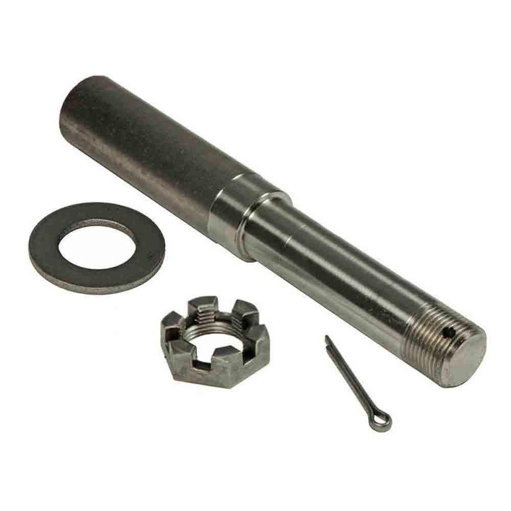
steel
Place of Origin
ZheJiang , China
Condition
New
Structure
Shaft
Coatings
Customized
Torque Capacity
Customized
Model Number
Customized
Brand Name
NON
Description
Shaft
Machining equipment
CNC mill,lathe and grind machine
Material
stainless steel, aluminium, carbon
Surface
Grinding and polishing
Shape
Customized
Sampling time
10days
Production time
20days
Packing
Protective packing
Tolerance
±0.001
OEM
Welcome
Production Process
Company Profile
HangZhou HUANENGDA SPRING CO.,LTD
HangZhou HuaNengDa Spring Co., Ltd. is located in Tong ‘an District, HangZhou City, ZheJiang Province, China. It is a hardware factory specializing in R&D design, manufacture and sales of precision components. The company introduces domestic and foreign advanced equipment and production technology, adopts CNC high-precision computer machine, compression spring machine, CNC five-axis linkage machining center, CNC turning and milling compound, 300 tons of punch and other mechanical equipment,and employs senior engineers with more than 10 years of work experience to debug mechanical equipment and customize production.
With the business philosophy of honesty, pragmatism and excellence, HuaNengDa Spring Company is dedicated to serving customers at home and abroad. We hope that the products of HuaNengDa will help your business to be more brilliant, let us build a bright future in the high-tech era!
The testimony is pragmatic and the attitude of the people. Quality service is the pursuit of the people!
Factory Workshop
Production Procedur
Quality Inspection
Packing And Shipping
Our Service
FAQ
1.Small order quantity is workable
From the initial sample design of the spring to the mass production of the springs, we can quickly reach your manufacturing goals and immediately provide the best products because we have an excellent production management system and expertly trained technical personnel.
2.Committed to high quality production
To keep HuaNengDa Springs at the forefront of the industry, we have implemented a stringent internal quality control system and regularly import the latest manufacturing equipment and instruments. Through our precise manufacturing technology and expert mold making process, we provide our customers with the best products and service.
3.Efficiency in manufacturing
Our company’s machinery and equipment are controlled by CNC computers. In order to respond to international needs and standards, we continuously update and upgrade our equipment every year. Our machines effectively increase production capacity and save on manufacturing costs. The manufacturing department is the most important core of the whole company and by treating it with utmost importance, we reap great benefits in manufacturing efficiency.
4.Excellent customization services
HuaNengDa’s R&D team designs and completes customized products according to the needs of customers. From the selection of materials to the function of the products, we can design and develop products to suite different customers’ requirements. We are constantly involving ourselves in all aspects of the industry because only by having a complete view and analysis of the industry, can there be innovative breakthroughs.
Payment term
*T/T : 30% pre T/T, 70% before delivery.
*Trade Assurance
Service
*Delivery on time.
*Shipped by a convenient and cost-effective way.
*Good after-selling, 24 hours service for you.
Packing
*A: Poly bag, Plstic tray ,small box, carton.
*B: According to customers’ requirements.
Delivery
*Sample: 7-10 days after deposit received.
*Batch goods: 12-15 days after samples approved.
| Condition: | New |
|---|---|
| Certification: | ISO9001 |
| Standard: | DIN, ASTM, GOST, GB, JIS, ANSI, BS |
| Customized: | Customized |
| Material: | Steel,Stainless Steel,Iron |
| Application: | Metal Processing Machinery Parts |
| Samples: |
US$ 10/Piece
1 Piece(Min.Order) | |
|---|
| Customization: |
Available
| Customized Request |
|---|
What is the relationship between the axle spindle and the wheel bearing in a vehicle?
In a vehicle, the axle spindle and the wheel bearing are two interconnected components that work together to allow the wheel to rotate smoothly and support the vehicle’s weight. Here’s a detailed explanation of their relationship:
The axle spindle is a key part of the vehicle’s suspension system, specifically in the axle assembly. It is a shaft-like component that protrudes from the axle housing and provides support for the wheel assembly. The spindle is typically located at the center of the wheel hub and serves as a mounting point for various components, including the wheel bearing.
The wheel bearing, on the other hand, is a set of precision-engineered bearings that are usually housed within a hub assembly. It is responsible for reducing friction and facilitating the smooth rotation of the wheel. The wheel bearing allows the wheel to spin freely while supporting the weight of the vehicle and enduring the forces generated during acceleration, braking, and cornering.
The relationship between the axle spindle and the wheel bearing is one of integration and mutual dependency. The axle spindle provides the structural support and attachment point for the wheel bearing assembly. The wheel bearing, in turn, enables the wheel to rotate with minimal friction and provides load-bearing capability.
When the vehicle is in motion, the axle spindle transfers the weight of the vehicle and the forces generated by the road surface to the wheel bearing. The wheel bearing, with its lubricated bearings and races, allows the wheel to rotate smoothly and evenly distribute the applied forces. This relationship ensures that the wheel assembly operates effectively, providing stability, control, and a comfortable ride.
Over time, the wheel bearing may experience wear and tear due to continuous use, exposure to contaminants, or lack of proper maintenance. When a wheel bearing becomes worn or damaged, it can lead to various symptoms such as excessive noise, vibration, uneven tire wear, or even wheel detachment. In such cases, it is necessary to replace the wheel bearing assembly, which often involves disassembling the axle spindle to access and replace the bearing.
It’s important to note that the specific design and configuration of the axle spindle and wheel bearing can vary between different vehicle models and manufacturers. Some vehicles may have integrated wheel bearing and hub assemblies, while others may have separate components that are assembled onto the spindle. It is recommended to consult the vehicle’s repair manual or seek professional assistance for specific instructions and procedures related to your vehicle.
In summary, the axle spindle and the wheel bearing have a close relationship in a vehicle’s suspension system. The axle spindle provides structural support and serves as the mounting point for the wheel bearing assembly. The wheel bearing, in turn, allows the wheel to rotate smoothly, supports the vehicle’s weight, and helps absorb the forces generated during driving. Understanding this relationship is important for proper maintenance, repair, and replacement of the wheel bearing assembly.
Can axle spindles be upgraded for improved performance, and if so, what are the options?
Axle spindles can be upgraded to improve the performance of a vehicle, particularly in applications where higher strength, durability, or enhanced capabilities are desired. Upgrading axle spindles can provide benefits such as increased load capacity, improved off-road capability, or enhanced towing capabilities. Here are some options for upgrading axle spindles:
- High-Strength Axle Spindles: One option is to replace the stock axle spindles with high-strength counterparts. High-strength axle spindles are typically made from stronger materials or feature reinforced designs to handle heavier loads or harsher conditions. These upgraded spindles can enhance the overall strength and durability of the axle assembly.
- Performance Axle Spindles: Performance-oriented axle spindles are designed to improve the handling and responsiveness of the vehicle. These spindles may feature optimized geometry, reduced weight, or enhanced stiffness to provide better cornering abilities, reduced body roll, or improved steering precision. Performance axle spindles are commonly used in applications such as racing or high-performance vehicles.
- Off-Road Axle Spindles: Off-road enthusiasts may opt for axle spindles specifically designed for rugged terrains. These spindles often have increased ground clearance, improved articulation, or additional reinforcement to withstand the demands of off-road driving. They can enhance the vehicle’s off-road capability, allowing for traversing challenging obstacles and rough terrain more effectively.
- Towing and Hauling Axle Spindles: Upgraded axle spindles for towing or hauling purposes are engineered to handle heavier loads and provide increased stability. These spindles may have reinforced construction, larger bearings, or specialized features such as integrated trailer brake connections. Upgrading to towing or hauling axle spindles can enhance the vehicle’s towing capacity and improve overall towing performance.
- Custom Axle Spindles: In some cases, custom axle spindles can be fabricated or modified to meet specific performance requirements. This option is typically utilized in specialized vehicle applications or when specific performance goals cannot be achieved with off-the-shelf upgrades. Custom axle spindles allow for tailored solutions that can address unique needs and performance objectives.
When considering axle spindle upgrades, it is essential to ensure compatibility with other components of the axle assembly, such as bearings, hubs, and brakes. Upgrades may also require modifications to other parts of the vehicle, such as suspension systems or steering components, to optimize performance and maintain overall safety and reliability.
It is recommended to consult with knowledgeable professionals, such as experienced mechanics, axle specialists, or vehicle customization experts, to determine the most suitable upgrade options for your specific vehicle and performance goals. They can provide guidance on selecting the appropriate axle spindle upgrades and ensure proper installation and integration into the vehicle’s overall system.
Can a failing axle spindle affect tire wear and alignment?
Yes, a failing axle spindle can indeed affect tire wear and alignment. Here’s a detailed explanation:
When an axle spindle is failing or damaged, it can have a direct impact on tire wear and alignment, leading to various issues. Here are some ways a failing axle spindle can affect tire wear and alignment:
- Uneven Tire Wear: A failing axle spindle can cause uneven tire wear patterns. The misalignment or instability resulting from a damaged spindle can lead to irregular contact between the tire and the road surface. This can cause specific areas of the tire to wear down more quickly than others. Common patterns of uneven tire wear include excessive wear on the edges or center of the tire, scalloping, cupping, or feathering. Uneven tire wear not only compromises tire lifespan but also affects vehicle handling and performance.
- Pulling or Drifting: A failing axle spindle can cause the vehicle to pull or drift to one side. This misalignment can be a result of the damaged spindle not allowing the wheels to be properly aligned. As a consequence, the tires on one side of the vehicle may experience increased friction and wear compared to the other side. This can lead to uneven tire wear and affect the vehicle’s stability and handling.
- Decreased Traction: A failing axle spindle can result in reduced traction between the tires and the road surface. Misalignment or instability caused by a damaged spindle can affect the tire’s ability to maintain optimal contact with the road. This can lead to decreased grip and traction, particularly during cornering or in wet or slippery conditions. Decreased traction not only affects tire wear but also compromises the vehicle’s overall safety and handling.
- Alignment Issues: A failing axle spindle can contribute to alignment problems. The damaged spindle may prevent the proper adjustment and alignment of the wheels. This can result in misaligned toe, camber, or caster angles, which directly impact tire wear. Improper alignment puts uneven stress on the tires, leading to accelerated wear and reduced tire lifespan.
- Compromised Steering Stability: A failing axle spindle can affect steering stability. Instability or misalignment caused by a damaged spindle can result in imprecise steering response and reduced control over the vehicle. This can lead to uneven tire loading and wear, as well as affect the overall handling and safety of the vehicle.
Addressing a failing axle spindle is crucial to prevent further damage to the tires and maintain proper alignment. If you notice uneven tire wear, pulling or drifting, decreased traction, or other signs of tire-related issues, it’s recommended to have the axle spindle inspected by a qualified mechanic or technician. They can accurately diagnose the problem and perform the necessary repairs or replacement to restore proper alignment and prevent further tire wear and damage.
In summary, a failing axle spindle can have a direct impact on tire wear and alignment. It can cause uneven tire wear, pulling or drifting, decreased traction, alignment issues, and compromised steering stability. Timely inspection and repair of the failing axle spindle are essential to ensure optimal tire performance, prolong tire lifespan, and maintain safe vehicle operation.
editor by CX 2023-11-27
China Good quality Customized Metal CNC Precision Machining Front Drive Shaft with Free Design Custom
Product Description
HangZhou Xihu (West Lake) Dis. Cardanshaft Co.,LTD is a leading professional manufacturer of cardan shafts in China. It is located in HangZhou ,ZheJiang Province. Our company has focused on the research and development , design and manufacture with different kinds of cardan shafts for almost 15 years.
Our producted cardan shafts are widely used in domestic large steel enterprises, such as ZheJiang Baosteel, HangZhou Iron and Steel Corporation, HangZhou Steel Corp and other domestic large-scale iron and steel enterprises.Now more products are exported to Europe, North America and Southeast Asia and other regions.
Our cardan shafts can be used to resist vibration and impact in the harsh environment of steel rolling, and the service life of cardan shafts is longer. We can also customize the special connection modes of cardan shafts in accordance of customers’ requirements .High precision, flexible joints, easy installation, perfect after-sales service and so on are highlight features of our products.
1.Product specification
1, advance technology
2, high accuracy and closely structure
3, high quality, the best price and good services
4, Strictly quality control by ISO9001: 2008.
5, with R&D Dept, OEM is available
2. About our advantages
1). With 10 years experience and professional OEM / ODM
2). Advance technology and R&D Dept with rich experience
3). Delivery in time
4).Competitive and reasonable price
5). High reputation
3.About our products
4.Application
Universal shafts with spider for industrial application commonly refer to cardan shaft .It is 1 of the most widely used transmission components. Our products are widely supplied to rubber and plastics machineries, petroleum machineries, wind-power testing equipments and bullet trains testing equipments, boat, agriculture machines etc.
Welcome to contact us if you are interested in products and want further details.
Looking forward to cooperating with you!
The Benefits of Spline Couplings for Disc Brake Mounting Interfaces
Spline couplings are commonly used for securing disc brake mounting interfaces. Spline couplings are often used in high-performance vehicles, aeronautics, and many other applications. However, the mechanical benefits of splines are not immediately obvious. Listed below are the benefits of spline couplings. We’ll discuss what these advantages mean for you. Read on to discover how these couplings work.
Disc brake mounting interfaces are splined
There are 2 common disc brake mounting interfaces – splined and six-bolt. Splined rotors fit on splined hubs; six-bolt rotors will need an adapter to fit on six-bolt hubs. The six-bolt method is easier to maintain and may be preferred by many cyclists. If you’re thinking of installing a disc brake system, it is important to know how to choose the right splined and center lock interfaces.
Aerospace applications
The splines used for spline coupling in aircraft are highly complex. While some previous researches have addressed the design of splines, few publications have tackled the problem of misaligned spline coupling. Nevertheless, the accurate results we obtained were obtained using dedicated simulation tools, which are not commercially available. Nevertheless, such tools can provide a useful reference for our approach. It would be beneficial if designers could use simple tools for evaluating contact pressure peaks. Our analytical approach makes it possible to find answers to such questions.
The design of a spline coupling for aerospace applications must be accurate to minimize weight and prevent failure mechanisms. In addition to weight reduction, it is necessary to minimize fretting fatigue. The pressure distribution on the spline coupling teeth is a significant factor in determining its fretting fatigue. Therefore, we use analytical and experimental methods to examine the contact pressure distribution in the axial direction of spline couplings.
The teeth of a spline coupling can be categorized by the type of engagement they provide. This study investigates the position of resultant contact forces in the teeth of a spline coupling when applied to pitch diameter. Using FEM models, numerical results are generated for nominal and parallel offset misalignments. The axial tooth profile determines the behavior of the coupling component and its ability to resist wear. Angular misalignment is also a concern, causing misalignment.
In order to assess wear damage of a spline coupling, we must take into consideration the impact of fretting on the components. This wear is caused by relative motion between the teeth that engage them. The misalignment may be caused by vibrations, cyclical tooth deflection, or angular misalignment. The result of this analysis may help designers improve their spline coupling designs and develop improved performance.
CZPT polyimide, an abrasion-resistant polymer, is a popular choice for high-temperature spline couplings. This material reduces friction and wear, provides a low friction surface, and has a low wear rate. Furthermore, it offers up to 50 times the life of metal on metal spline connections. For these reasons, it is important to choose the right material for your spline coupling.
High-performance vehicles
A spline coupler is a device used to connect splined shafts. A typical spline coupler resembles a short pipe with splines on either end. There are 2 basic types of spline coupling: single and dual spline. One type attaches to a drive shaft, while the other attaches to the gearbox. While spline couplings are typically used in racing, they’re also used for performance problems.
The key challenge in spline couplings is to determine the optimal dimension of spline joints. This is difficult because no commercial codes allow the simulation of misaligned joints, which can destroy components. This article presents analytical approaches to estimating contact pressures in spline connections. The results are comparable with numerical approaches but require special codes to accurately model the coupling operation. This research highlights several important issues and aims to make the application of spline couplings in high-performance vehicles easier.
The stiffness of spline assemblies can be calculated using tooth-like structures. Such splines can be incorporated into the spline joint to produce global stiffness for torsional vibration analysis. Bearing reactions are calculated for a certain level of misalignment. This information can be used to design bearing dimensions and correct misalignment. There are 3 types of spline couplings.
Major diameter fit splines are made with tightly controlled outside diameters. This close fit provides concentricity transfer from the male to the female spline. The teeth of the male spline usually have chamfered tips and clearance with fillet radii. These splines are often manufactured from billet steel or aluminum. These materials are renowned for their strength and uniform grain created by the forging process. ANSI and DIN design manuals define classes of fit.
Disc brake mounting interfaces
A spline coupling for disc brake mounting interfaces is a type of hub-to-brake-disc mount. It is a highly durable coupling mechanism that reduces heat transfer from the disc to the axle hub. The mounting arrangement also isolates the axle hub from direct contact with the disc. It is also designed to minimize the amount of vehicle downtime and maintenance required to maintain proper alignment.
Disc brakes typically have substantial metal-to-metal contact with axle hub splines. The discs are held in place on the hub by intermediate inserts. This metal-to-metal contact also aids in the transfer of brake heat from the brake disc to the axle hub. Spline coupling for disc brake mounting interfaces comprises a mounting ring that is either a threaded or non-threaded spline.
During drag brake experiments, perforated friction blocks filled with various additive materials are introduced. The materials included include Cu-based powder metallurgy material, a composite material, and a Mn-Cu damping alloy. The filling material affects the braking interface’s wear behavior and friction-induced vibration characteristics. Different filling materials produce different types of wear debris and have different wear evolutions. They also differ in their surface morphology.
Disc brake couplings are usually made of 2 different types. The plain and HD versions are interchangeable. The plain version is the simplest to install, while the HD version has multiple components. The two-piece couplings are often installed at the same time, but with different mounting interfaces. You should make sure to purchase the appropriate coupling for your vehicle. These interfaces are a vital component of your vehicle and must be installed correctly for proper operation.
Disc brakes use disc-to-hub elements that help locate the forces and displace them to the rim. These elements are typically made of stainless steel, which increases the cost of manufacturing the disc brake mounting interface. Despite their benefits, however, the high braking force loads they endure are hard on the materials. Moreover, excessive heat transferred to the intermediate elements can adversely affect the fatigue life and long-term strength of the brake system.


China Custom High Performance Ball Screw Fittings Quincunx Aluminum Alloy CZPT Elastic Servo Motor Ball Screw CNC Lathe Star CZPT Joint Shaft near me shop
Product Description
The ball screw assembly consists of a ball screw nut and a support seat at both ends of the rod. Its function is to convert rotating motion into straight motion or straight motion into rotating motion. Ball screws are widely used in various industrial equipment and precision instruments.
Ball screw accessories can also be purchased in our shop, or directly consult online customer service to help you buy
Company Profile
ZHangZhoug HangZhou KaiYaDe bearing co., LTD. Is a have many years experience of linear motion products professional manufacturers. We specialized in the production of straight axis, linear guide, ball screw, linear bearings, linear guide, ball screw end support, linear guide, CAM follower and of good quality and competitive price. My company is located in HangZhou city, zHangZhoug province, close to HangZhou port and HangZhou city.
Our Advantages
FAQ
1. Are you a factory or trading company?
We are the most competitive price and high quality professional manufacturers, has 12 years of experience.
2. What is your product range?
Specializing in the production of straight axis, linear bearings, linear guide, linear guide, ball screw, linear motion unit such as CAM follower.
3. Do you provide OEM&ODM service?
B: yes. Welcome OEM, ODM
4. How can I get some samples?
We are very honored to provide samples. You need to pay the freight and some sample fee.
5. How is the quality control of your factory?
We uphold the tenet of “quality is the future”, we have passed CE certification, we have strict quality control procedures.
6. How can I get quotation?
You can send below quotation or send email to us. You can contact us directly by TM or WhatsApp and Skype as you like. If you have an emergency, please call us at any time.
The Benefits of Spline Couplings for Disc Brake Mounting Interfaces
Spline couplings are commonly used for securing disc brake mounting interfaces. Spline couplings are often used in high-performance vehicles, aeronautics, and many other applications. However, the mechanical benefits of splines are not immediately obvious. Listed below are the benefits of spline couplings. We’ll discuss what these advantages mean for you. Read on to discover how these couplings work.
Disc brake mounting interfaces are splined
There are 2 common disc brake mounting interfaces – splined and six-bolt. Splined rotors fit on splined hubs; six-bolt rotors will need an adapter to fit on six-bolt hubs. The six-bolt method is easier to maintain and may be preferred by many cyclists. If you’re thinking of installing a disc brake system, it is important to know how to choose the right splined and center lock interfaces.
Aerospace applications
The splines used for spline coupling in aircraft are highly complex. While some previous researches have addressed the design of splines, few publications have tackled the problem of misaligned spline coupling. Nevertheless, the accurate results we obtained were obtained using dedicated simulation tools, which are not commercially available. Nevertheless, such tools can provide a useful reference for our approach. It would be beneficial if designers could use simple tools for evaluating contact pressure peaks. Our analytical approach makes it possible to find answers to such questions.
The design of a spline coupling for aerospace applications must be accurate to minimize weight and prevent failure mechanisms. In addition to weight reduction, it is necessary to minimize fretting fatigue. The pressure distribution on the spline coupling teeth is a significant factor in determining its fretting fatigue. Therefore, we use analytical and experimental methods to examine the contact pressure distribution in the axial direction of spline couplings.
The teeth of a spline coupling can be categorized by the type of engagement they provide. This study investigates the position of resultant contact forces in the teeth of a spline coupling when applied to pitch diameter. Using FEM models, numerical results are generated for nominal and parallel offset misalignments. The axial tooth profile determines the behavior of the coupling component and its ability to resist wear. Angular misalignment is also a concern, causing misalignment.
In order to assess wear damage of a spline coupling, we must take into consideration the impact of fretting on the components. This wear is caused by relative motion between the teeth that engage them. The misalignment may be caused by vibrations, cyclical tooth deflection, or angular misalignment. The result of this analysis may help designers improve their spline coupling designs and develop improved performance.
CZPT polyimide, an abrasion-resistant polymer, is a popular choice for high-temperature spline couplings. This material reduces friction and wear, provides a low friction surface, and has a low wear rate. Furthermore, it offers up to 50 times the life of metal on metal spline connections. For these reasons, it is important to choose the right material for your spline coupling.
High-performance vehicles
A spline coupler is a device used to connect splined shafts. A typical spline coupler resembles a short pipe with splines on either end. There are 2 basic types of spline coupling: single and dual spline. One type attaches to a drive shaft, while the other attaches to the gearbox. While spline couplings are typically used in racing, they’re also used for performance problems.
The key challenge in spline couplings is to determine the optimal dimension of spline joints. This is difficult because no commercial codes allow the simulation of misaligned joints, which can destroy components. This article presents analytical approaches to estimating contact pressures in spline connections. The results are comparable with numerical approaches but require special codes to accurately model the coupling operation. This research highlights several important issues and aims to make the application of spline couplings in high-performance vehicles easier.
The stiffness of spline assemblies can be calculated using tooth-like structures. Such splines can be incorporated into the spline joint to produce global stiffness for torsional vibration analysis. Bearing reactions are calculated for a certain level of misalignment. This information can be used to design bearing dimensions and correct misalignment. There are 3 types of spline couplings.
Major diameter fit splines are made with tightly controlled outside diameters. This close fit provides concentricity transfer from the male to the female spline. The teeth of the male spline usually have chamfered tips and clearance with fillet radii. These splines are often manufactured from billet steel or aluminum. These materials are renowned for their strength and uniform grain created by the forging process. ANSI and DIN design manuals define classes of fit.
Disc brake mounting interfaces
A spline coupling for disc brake mounting interfaces is a type of hub-to-brake-disc mount. It is a highly durable coupling mechanism that reduces heat transfer from the disc to the axle hub. The mounting arrangement also isolates the axle hub from direct contact with the disc. It is also designed to minimize the amount of vehicle downtime and maintenance required to maintain proper alignment.
Disc brakes typically have substantial metal-to-metal contact with axle hub splines. The discs are held in place on the hub by intermediate inserts. This metal-to-metal contact also aids in the transfer of brake heat from the brake disc to the axle hub. Spline coupling for disc brake mounting interfaces comprises a mounting ring that is either a threaded or non-threaded spline.
During drag brake experiments, perforated friction blocks filled with various additive materials are introduced. The materials included include Cu-based powder metallurgy material, a composite material, and a Mn-Cu damping alloy. The filling material affects the braking interface’s wear behavior and friction-induced vibration characteristics. Different filling materials produce different types of wear debris and have different wear evolutions. They also differ in their surface morphology.
Disc brake couplings are usually made of 2 different types. The plain and HD versions are interchangeable. The plain version is the simplest to install, while the HD version has multiple components. The two-piece couplings are often installed at the same time, but with different mounting interfaces. You should make sure to purchase the appropriate coupling for your vehicle. These interfaces are a vital component of your vehicle and must be installed correctly for proper operation.
Disc brakes use disc-to-hub elements that help locate the forces and displace them to the rim. These elements are typically made of stainless steel, which increases the cost of manufacturing the disc brake mounting interface. Despite their benefits, however, the high braking force loads they endure are hard on the materials. Moreover, excessive heat transferred to the intermediate elements can adversely affect the fatigue life and long-term strength of the brake system.
China best Shaft Collars Nonstandard Set Screw CNC Machined Split Shaft Collar near me shop
Product Description
High quality double split shaft collar stainless steel precision shaft clamp
| Model | Bore Size | O.D. | Width | Screw | Approx.Weight |
| (g) | |||||
| ISC-12 | 3/16 | 7/16 | 1/4 | 8-32×1/8 | 3.9 |
| ISC-18 | 1/4 | 1/2 | 9/32 | 8-32×1/8 | 5.3 |
| ISC-25 | 5/16 | 5/8 | 11/32 | 10-32×5/32 | 10.2 |
| ISC-31 | 3/8 | 3/4 | 3/8 | 1/4-20×3/16 | 16 |
| ISC-37 | 7/16 | 7/8 | 7/16 | 1/4-20×1/4 | 25.4 |
| ISC-43 | 1/2 | 1 | 7/16 | 1/4-20×1/4 | 33.2 |
| ISC-50 | 9/16 | 1 | 7/16 | 1/4-20×1/4 | 30.3 |
| ISC-56 | 5/8 | 1 1/8 | 1/2 | 5/16-18×1/4 | 44.2 |
| ISC-62 | 11/16 | 1 1/4 | 9/16 | 5/16-18×1/4 | 62 |
| ISC-68 | 3/4 | 1 1/4 | 9/16 | 5/16-18×1/4 | 56.9 |
| ISC-75 | 13/16 | 1 5/16 | 9/16 | 5/16-18×1/4 | 60.4 |
| ISC-81 | 7/8 | 1 1/2 | 9/16 | 5/16-18×5/16 | 84.4 |
| ISC-87 | 15/16 | 1 5/8 | 9/16 | 5/16-18×5/16 | 100.2 |
| ISC-93 | 1 | 1 5/8 | 5/8 | 5/16-18×5/16 | 103.6 |
| ISC-100 | 1 1/16 | 1 3/4 | 5/8 | 5/16-18×5/16 | 122.1 |
| ISC-106 | 1 1/8 | 1 3/4 | 5/8 | 5/16-18×5/16 | 113.5 |
| ISC-112 | 1 3/16 | 2 | 11/16 | 3/8-16×3/8 | 180 |
Product Features:
1.Effective on hard and soft shafts
2.Cost effective collar design
3.Easily installed where major disassembly would otherwise be required Simply slide these collars onto a shaft and tighten the set screw to hold the collar in place.Collars are easy to adjust with their set screws.
Types of shaft collars:
Solid Setscrew shaft collar,Hex bore shaft collar,One Piece shaft collar,Two
Piece shaft collar,Threaded shaft collar,Single split shaft collar,Double split shaft collar
Our products can be made according to Climax,Holo-Krome,Stafford,Ruland etc.
Note of single split shaft collar:
1.Material:AL,Steel,Stainless steel,Alloy,Copper,Plastic
2.Finish: Black oxide, self-color, oiled, zinc plated
3.Processes:Broaching/ Hobbing/ Slotting/tapping
4.Package:box/carton/wooden case
5.Lead time:20-35 days
6.ISO9001:2008 Certificated
Use:
single split shaft collars are used in a variety of application and industries. Examples include agricultural implements, office machines, exercise equipment, mixers, and printing presses.A variety of specialized products are available. Knurled shaft collars provide a friction surface for hand gripping and are suitable for conveyors and other applications which require frequent collar adjustment.
Hexagonal-bore shaft collars are suitable for power transmission and drive applications.
Heavy-duty shaft collars feature large cross sections and sturdy clamping screws for added holding power.
Because heavy-duty shaft collars provide better vibration and shock resistance,
they are designed for applications such as off-road, mining, paper and steel mill equipment.
Main Products:
1. Timing Belt Pulley (Synchronous Pulley), Timing Bar, Clamping Plate;
2. Forging, Casting, Stampling Part;
3. V Belt Pulley and Taper Lock Bush; Sprocket, Idler and Plate Wheel;Spur Gear, Bevel Gear, Rack;
4. Shaft Locking Device: could be alternative for Ringfeder, Sati, Chiaravalli, Tollok, etc.;
5. Shaft Coupling:including Miniature couplings, Curved tooth coupling, Chain coupling, HRC coupling, Normex coupling, Type coupling, GE Coupling, torque limiter, Universal Joint;
6. Shaft Collars: including Setscrew Type, Single Split and Double Splits;
7. Gear & Rack: Spur gear/rack, bevel gear, helical gear/rack
8. Other customized Machining Parts according to drawings (OEM).
PACKING
| Packaging | |
| Packing
|
We use standard export wooden case, carton and pallet, but we can also pack it as per your special requirements. |
OUR COMPANY
ZheJiang Mighty Machinery Co., Ltd. specializes in offering best service and the most competitive price for our customer.
After over 10 years’ hard work, MIGHTY’s business has grown rapidly and become an important partner for oversea clients in the industrial field and become a holding company for 3 manufacturing factories.
MIGHTY’s products have obtained reputation of domestic and oversea customers with taking advantage of technology, management, quality and very competitive price.
Your satisfaction is the biggest motivation for our work, choose us to get high quality products and best service.
OUR FACTORY
FAQ
Q: Are you trading company or manufacturer ?
A: We are factory.
Q: How long is your delivery time?
A: Generally it is 5-10 days if the goods are in stock. or it is 15-20 days if the goods are not in stock, it is according to quantity.
Q: Do you provide samples ? is it free or extra ?
A: Yes, we could offer the sample for free charge but do not pay the cost of freight.
Q: What is your terms of payment ?
A: Payment=1000USD, 30% T/T in advance ,balance before shippment.
We warmly welcome friends from domestic and abroad come to us for business negotiation and cooperation for mutual benefit.To supply customers excellent quality products with good price and punctual delivery time is our responsibility.
The Functions of Splined Shaft Bearings
Splined shafts are the most common types of bearings for machine tools. They are made of a wide variety of materials, including metals and non-metals such as Delrin and nylon. They are often fabricated to reduce deflection. The tooth profile will become deformed with time, as the shaft is used over a long period of time. Splined shafts are available in a huge range of materials and lengths.
Functions
Splined shafts are used in a variety of applications and industries. They are an effective anti-rotational device, as well as a reliable means of transmitting torque. Other types of shafts are available, including key shafts, but splines are the most convenient for transmitting torque. The following article discusses the functions of splines and why they are a superior choice. Listed below are a few examples of applications and industries in which splines are used.
Splined shafts can be of several styles, depending on the application and mechanical system in question. The differences between splined shaft styles include the design of teeth, overall strength, transfer of rotational concentricity, sliding ability, and misalignment tolerance. Listed below are a few examples of splines, as well as some of their benefits. The difference between these styles is not mutually exclusive; instead, each style has a distinct set of pros and cons.
A splined shaft is a cylindrical shaft with teeth or ridges that correspond to a specific angular position. This allows a shaft to transfer torque while maintaining angular correspondence between tracks. A splined shaft is defined as a cylindrical member with several grooves cut into its circumference. These grooves are equally spaced around the shaft and form a series of projecting keys. These features give the shaft a rounded appearance and allow it to fit perfectly into a grooved cylindrical member.
While the most common applications of splines are for shortening or extending shafts, they can also be used to secure mechanical assemblies. An “involute spline” spline has a groove that is wider than its counterparts. The result is that a splined shaft will resist separation during operation. They are an ideal choice for applications where deflection is an issue.
A spline shaft’s radial torsion load distribution is equally distributed, unless a bevel gear is used. The radial torsion load is evenly distributed and will not exert significant load concentration. If the spline couplings are not aligned correctly, the spline connection can fail quickly, causing significant fretting fatigue and wear. A couple of papers discuss this issue in more detail.
Types
There are many different types of splined shafts. Each type features an evenly spaced helix of grooves on its outer surface. These grooves are either parallel or involute. Their shape allows them to be paired with gears and interchange rotary and linear motion. Splines are often cold-rolled or cut. The latter has increased strength compared to cut spines. These types of shafts are commonly used in applications requiring high strength, accuracy, and smoothness.
Another difference between internal and external splined shafts lies in the manufacturing process. The former is made of wood, while the latter is made of steel or a metal alloy. The process of manufacturing splined shafts involves cutting furrows into the surface of the material. Both processes are expensive and require expert skill. The main advantage of splined shafts is their adaptability to a wide range of applications.
In general, splined shafts are used in machinery where the rotation is transferred to an internal splined member. This member can be a gear or some other rotary device. These types of shafts are often packaged together as a hub assembly. Cleaning and lubricating are essential to the life of these components. If you’re using them on a daily basis, you’ll want to make sure to regularly inspect them.
Crowned splines are usually involute. The teeth of these splines form a spiral pattern. They are used for smaller diameter shafts because they add strength. Involute splines are also used on instrument drives and valve shafts. Serration standards are found in the SAE. Both kinds of splines can also contain a ball bearing for high torque. The difference between the 2 types of splines is the number of teeth on the shaft.
Internal splines have many advantages over external ones. For example, an internal spline shaft can be made using a grinding wheel instead of a CNC machine. It also uses a more accurate and economical process. Furthermore, it allows for a shorter manufacturing cycle, which is essential when splining high-speed machines. In addition, it stabilizes the relative phase between the spline and thread.
Manufacturing methods
There are several methods used to fabricate a splined shaft. Key and splined shafts are constructed from 2 separate parts that are shaped in a synchronized manner to transfer torque uniformly. Hot rolling is 1 method, while cold rolling utilizes low temperatures to form metal. Both methods enhance mechanical properties, surface finishes, and precision. The advantage of cold rolling is its cost-effectiveness.
Cold forming is 1 method, as well as machining and assembling. Cold forming is a unique process that allows the spline to be shaped to the desired shape. The resulting shape provides maximum contact area and torsional strength. Standard splines are available in standard sizes, but custom lengths can also be ordered. CZPT offers various auxiliary equipment, such as mating sleeves and flanged bushings.
Cold forging is another method. This method produces long splined shafts that are used in automobile propellers. After the spline portion is cut out, it is worked on in a hobbing machine. Work hardening enhances the root strength of the splined portion. It can be used for bearings, gears, and other mechanical components. Listed below are the manufacturing methods for splined shafts.
Parallel splines are the simplest of the splined shaft manufacturing methods. Parallel splines are usually welded to shafts, while involute splines are made of metal or non-metals. Splines are available in a wide variety of lengths and materials. The process is usually accompanied by a process called milling. The workpiece rotates to produce the serrated surface.
Splines are internal or external grooves in a splined shaft. They work in combination with keyways to transfer torque. Male and female splines are used in gears. Female and male splines correspond to 1 another to ensure proper angular correspondence. Involute splines have more surface area and thus are stronger than external splines. Moreover, they help the shaft fit into a grooved cylindrical member without misalignment.
A variety of other methods of manufacturing a splined shaft can be used to produce a splined shaft. Spline shafts can be produced using broaching and shaping, 2 precision machining methods. Broaching uses a metal tool with successively larger teeth to remove metal and create ridges and holes in the surface of a material. However, this process is expensive and requires special expertise.
Applications
The splined shaft is a mechanical component with a helix-like shape formed by the equal spacing of grooves in a circular ring. The splines can either have parallel or involute sides. The splines minimize stress concentration in stationary joints and can be used in both rotary and linear motion. In some cases, splines are rolled rather than cut. The latter is more durable than cut splines and is often used in applications requiring high strength, accuracy, and smooth finish.
Splined shafts are commonly made of carbon steel. This alloy steel has a low carbon content, making it easy to work with. Carbon steel is a great choice for splines because it is malleable. Generally, high-quality carbon steel provides a consistent motion. Steel alloys are also available that contain nickel, chromium, copper, and other metals. If you’re unsure of the right material for your application, you can consult a spline chart.
Splines are a versatile mechanical component. They are easy to cut and fit. Splines can be internal or external, with teeth positioned at equal intervals on both sides of the shaft. This allows the shaft to engage with the hub around the entire circumference of the hub. It also increases load capacity by creating a constant multiple-tooth point of contact with the hub. For this reason, they’re used extensively in rotary and linear motion.
Splined shafts are used in a wide variety of industries. CZPT Inc. offers custom and standard splined shafts for a variety of applications. When choosing a splined shaft for a specific application, consider the surrounding mated components, torque requirements, and size requirements. These 3 factors will make it the ideal choice for your rotary equipment. And you’ll be pleased with the end result!
There are many types of splines and their applications are endless. They transfer torque and angular misalignment between parts, and they also enable the axial rotation of assembled components. Therefore, splines are an essential component of machinery and are used in a wide range of applications. This type of shaft can be found in various types of machines, from household appliances to industrial machinery. So, the next time you’re looking for a splined shaft, make sure you look for a splined one.